
Every step of drawing in 3D is now built. Chapter 29 placed an object with a model matrix, Chapter 31 built the view, and Chapter 30 built the projection, the divide and the stretch across the window. Chapter 31 clipped lines at the near plane, too. This chapter puts the steps in one line, in the order a corner travels them, and runs real models through it: meshes of corners and faces, some built into the program and one loaded from a file.
There's no new mathematics here. It's assembly, along with a few choices every renderer makes. One matrix does the first three steps. The clip moves into clip space, where that one matrix leaves the corners. Each corner is transformed once, and each edge is drawn once. And one corner of a cube is followed all the way from its own space to its pixel, with the demo's own numbers.
In this chapter, we will:
- Put the model, view and projection matrices together into one
- Clip in clip space, where the one matrix leaves the corners
- Follow one corner from a mesh's own space to a pixel
- Store a mesh as corners and faces, and draw each edge once
- Load meshes from
.objfiles, and turn their faces the right way round - Orbit a camera around a model
- Build Mesh Viewer, which draws four meshes in wireframe
We'll start with the whole pipeline.
The Pipeline
Five Steps and a Clip
A corner of a model goes through five steps, from the model's own space to a pixel:
- The model matrix places it in the world, as in Chapter 29.
- The view matrix takes it into view space, as in Chapter 31.
- The projection matrix takes it to clip space, as in Chapter 30.
- The divide by w takes it to NDC.
- The viewport stretches NDC across the window, to pixels.
Between steps 3 and 4 comes the clip at the near plane, which keeps every w safe to divide by. The next image shows the whole line, with the space a corner is in after each step.
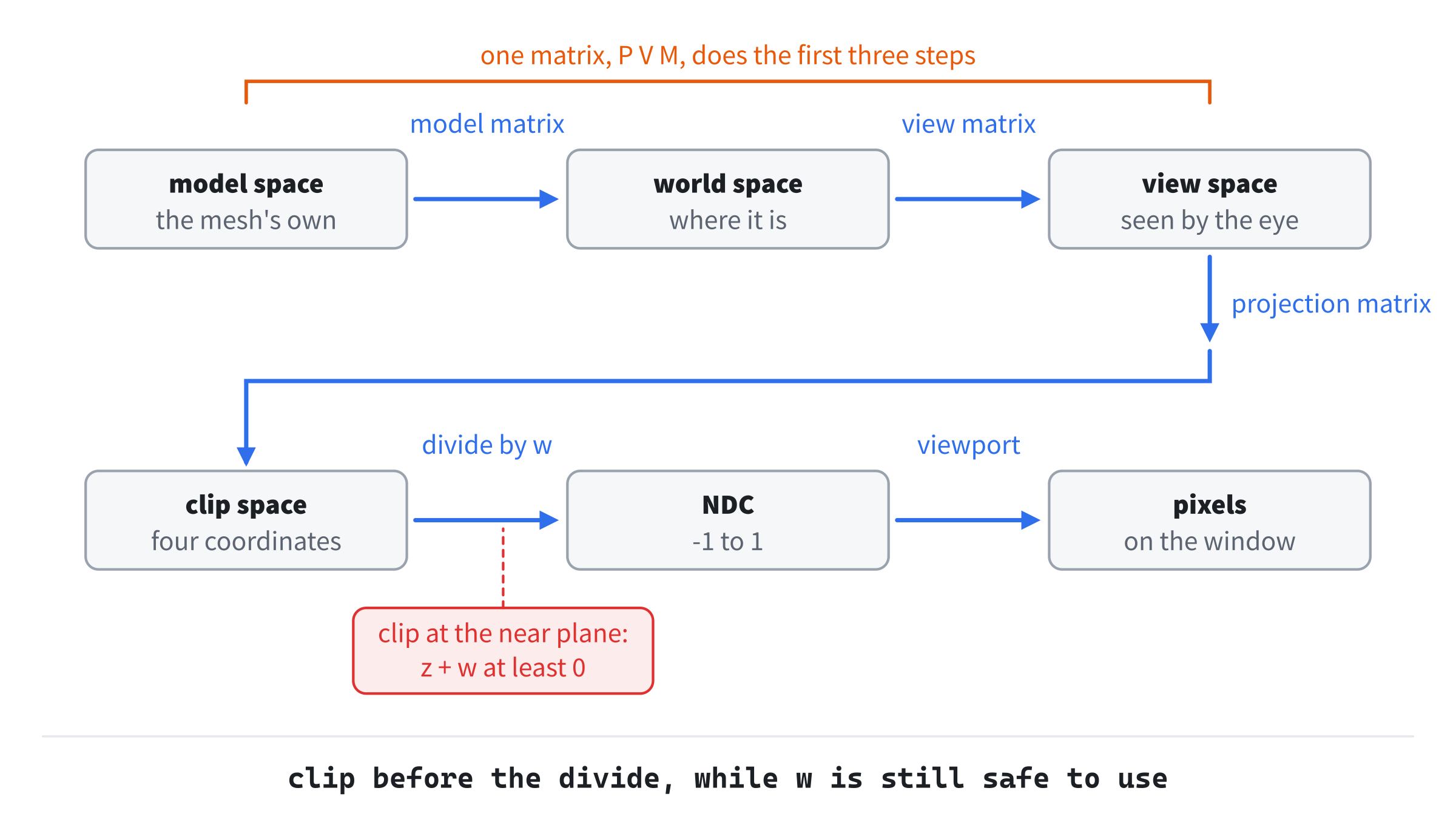
Every corner of every model takes this path, every frame. The order matters, since each step expects its input in the space the step before leaves it in. A projection applied to world space, before the view, would flatten the world from the origin, not from the camera.
One Matrix
The first three steps are matrices, and Chapter 26 found that matrices multiply into one that does both. So one matrix does all three:
MVP = P V MRead from the right, it applies the model matrix first, then the view, then the projection. It's built once a frame for each object, at the cost of two products. Then each corner costs one apply4, instead of three. Engines call it the MVP matrix, and send it to the graphics card with every object.
Clipping in Clip Space
With one matrix, the corners go straight from their own space to clip space, and view space is never seen. So the clip has to happen in clip space. Chapter 30 found the near plane's test there: a point is beyond the near plane when z is at least -w. That's when z + w is at least 0, so z + w works as the point's distance beyond the plane.
Along an edge, a point's clip coordinates are a straight-line mix of its ends', since the matrix is a sum of products. So z + w changes in a straight line too, and the edge crosses the plane where it's 0. With da and db for the ends' values of z + w:
t = da / (da - db)That's Chapter 31's t, found in clip space instead. For an edge of the cube seen from inside it, both ways give 0.6242. The moved end is the mix of the ends' four coordinates at that t. This is why the space is called clip space: it's where clipping is done, before the divide. A graphics card clips there against all six planes of the frustum.
One Corner, End to End
Follow corner 6 of Mesh Viewer's cube, (1, 1, 1), at the start. The cube isn't yet turned, so the model matrix is the identity, and the corner is at (1, 1, 1) in the world too. The eye is at (2.60, 1.95, 3.80), 5 units from the middle, looking at it. The view takes the corner to:
view = (0.261, 0.380, -3.330)It's 3.33 in front of the eye, and a little to the right and up. The projection is Chapter 30's, with a field of view of 60 degrees and planes at 0.1 and 100, so A is -1.002 and B is -0.200. It takes the corner to clip space:
x = 1.212 * 0.261 = 0.316
y = 1.732 * 0.380 = 0.658
z = -1.002 * -3.330 - 0.200 = 3.137
w = 3.330
Its z + w is 6.47, so it's beyond the near plane, and it isn't clipped. The divide gives NDC:
(0.316 / 3.330, 0.658 / 3.330, 3.137 / 3.330) = (0.095, 0.198, 0.942)The viewport puts it 0.547 of the way across the window and 0.401 of the way down. That's the pixel (547, 281), a little right of the middle and above it, as a near corner of a cube seen from above and to the right should be. The one matrix, P V M, gives exactly the same clip coordinates in one step.
Meshes
Corners and Faces
A model is a mesh: a list of corners, and a list of faces. Each face is a loop of numbers, indices into the list of corners, in order around the face. A triangle has three, a square four, and any flat polygon as many as it has corners. A corner shared by several faces is stored once, and each face names it by its number, as Chapter 24's indices did. The next image shows the built-in cube, with its corners numbered.
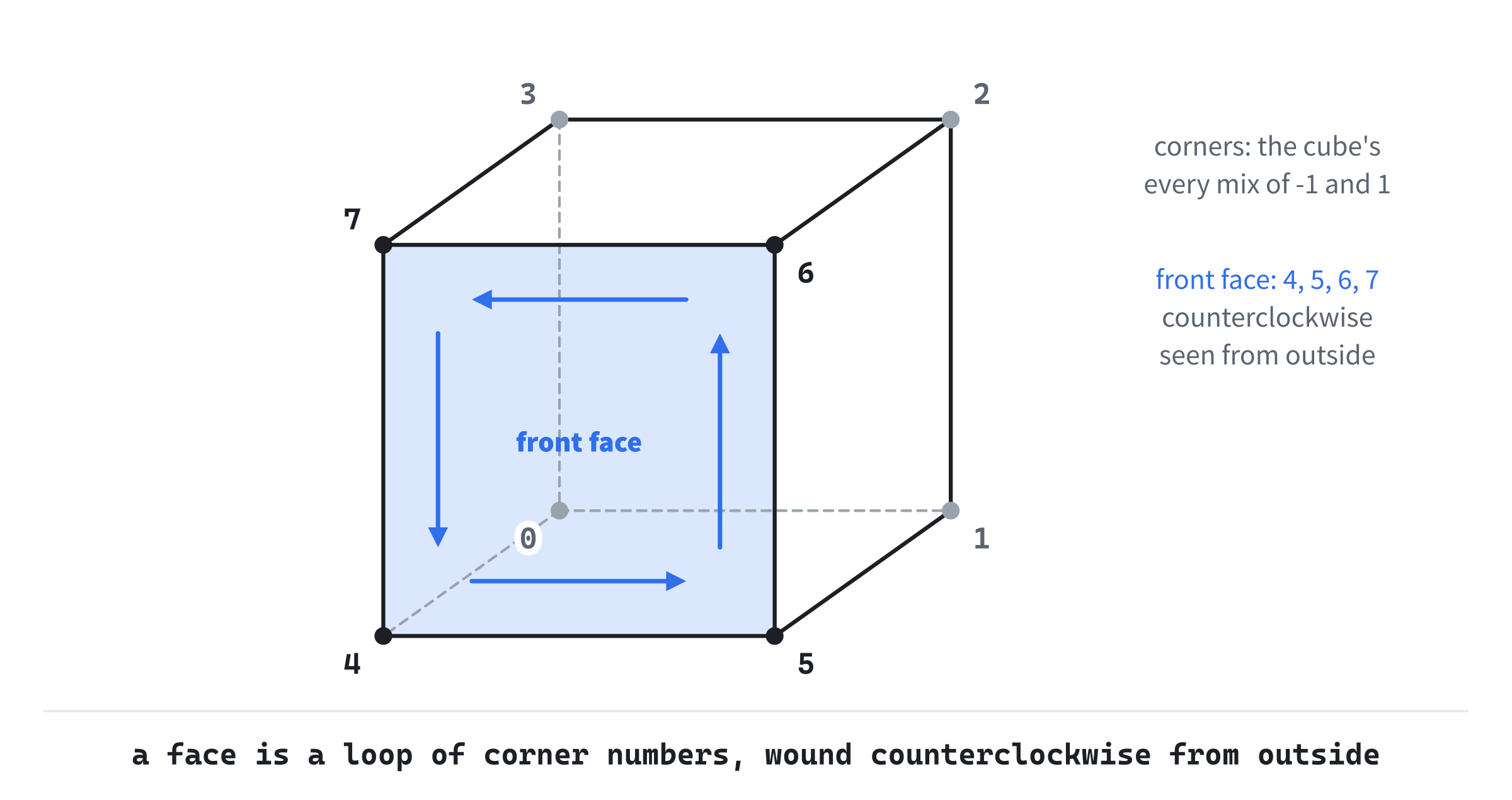
The order of a face's loop is its winding. Every face here is wound counterclockwise as seen from outside, so that Chapter 28's cross product of its edges points out of the mesh. The front face's loop is 4, 5, 6, 7: along the bottom, up the right side, back along the top and down. Seen from inside, the same loop runs clockwise. Chapter 33 uses the winding to tell the faces turned toward the camera from those turned away. The mesh stores nothing else. Chapter 33 works out each triangle's normal from its corners, and Chapter 34 keeps texture coordinates with each triangle.
Each Edge Once
A face's loop gives its edges: each corner to the next, and the last back to the first. Drawing every face's loop draws every edge, but in a closed mesh each edge belongs to two faces, so it's drawn twice. Transforming the corners edge by edge is worse. A cube's corner is in three faces, and each of those faces uses it in two edges, so it's transformed six times a frame. A cube drawn that way costs 48 transforms and 24 lines, and Mesh Viewer's way costs 8 transforms and 12 lines. Each corner is transformed once, into a list, and each edge is drawn once, from a list of edges made when the mesh is chosen.
Loading Meshes
The .obj Format
Typing meshes into the code gets old fast. Every 3D tool can export a Wavefront .obj file, which is plain text, a line for each thing. A line starting v is a corner, its x, y and z. A line starting f is a face, a list of corner numbers. The numbers count from 1, not 0, and a negative number counts back from the last corner so far, so that -1 is the latest. A face's corner can also be written as three numbers with slashes, such as 12/3/4. The first is the corner, and the others name texture coordinates and normals, from lines that this book's loader skips. Here's Mesh Viewer's pyramid.obj:
# A square pyramid, for Mesh Viewer (Chapter 32): five corners, a square
# base and four triangles. The triangles are listed clockwise from outside,
# the wrong way round, which the loader puts right.
v -1 0 -1
v 1 0 -1
v 1 0 1
v -1 0 1
v 0 1.8 0
f 1 2 3 4
f 1 2 5
f 2 3 5
f 3 4 5
f 4 1 5
Lines starting # are comments. The base is the first face, a square, and the four triangles run from each side of the base up to the top corner.
Two Fixes
A file's mesh can be anywhere, and its faces can be wound either way. The loader fixes both, with four functions in the new header, Mesh.h. The header starts with the mesh itself:
#pragma once
#include <algorithm>
#include <fstream>
#include <sstream>
#include <string>
#include <vector>
#include "Vec3.h"

// Mesh: a model as a list of corners and a list of faces (Chapter 32). Each
// face is a loop of indices into the corners, counterclockwise as seen from
// outside: three for a triangle, four for a square, or more.
struct Mesh
{
    std::string name;
    std::vector<Vec3> verts;
    std::vector<std::vector<int>> faces;
};
A face is a std::vector<int>, so a mesh's faces are a vector of vectors, and a face can have any number of corners. The name is for the readout. The first fix moves the mesh to the middle. It needs the mesh's center, the average of its corners:
// The average of a mesh's corners, which is inside it when it's convex.
inline Vec3 meshCenter(const Mesh& m)
{
    Vec3 sum;
    for (Vec3 v : m.verts) sum += v;
    return m.verts.empty() ? sum : sum / (float)m.verts.size();
}
For a mesh with no corners, it returns the zero vector rather than dividing by 0. Then every corner is moved by minus the center:
// Move a mesh so that the average of its corners is at the origin, so that
// it turns about its middle.
inline void recenter(Mesh& m)
{
    Vec3 c = meshCenter(m);
    for (Vec3& v : m.verts) v -= c;
}
Now the mesh turns about its own middle, rather than swinging about some point to one side. The second fix needs each face's normal:
// A face's normal: the sum of the cross products of its fan of triangles,
// each from its first corner. A face whose first three corners lie on one
// line still gets its normal from the others.
inline Vec3 faceNormal(const Mesh& m, const std::vector<int>& f)
{
    Vec3 n;
    for (size_t k = 1; k + 1 < f.size(); ++k)
        n += (m.verts[f[k]] - m.verts[f[0]]).cross(m.verts[f[k + 1]] -
                                                   m.verts[f[0]]);
    return n;
}
A face with more than three corners is a fan of triangles from its first corner, and their cross products all point the same way, since the face is flat. Their sum is the face's normal, twice as long as its area. Taking only the first triangle's cross product would usually do, but not for a face whose first three corners lie on one line, such as a square with an extra corner in the middle of an edge. That cross product is zero, while the sum still has the others. Then each face is checked against the mesh's center:
// Reverse every face whose normal points in toward the mesh's center, so
// that every face is counterclockwise from outside. That's right for a
// convex mesh, whose center is inside every face's back.
inline void fixWinding(Mesh& m)
{
    Vec3 c = meshCenter(m);
    for (std::vector<int>& f : m.faces)
    {
        Vec3 middle;
        for (int i : f) middle += m.verts[i];
        middle = middle / (float)f.size();
        if (faceNormal(m, f).dot(middle - c) < 0.0f)
            std::reverse(f.begin(), f.end());
    }
}
A face wound the right way has a normal pointing away from the center, out of the mesh. So if the normal's dot product with the way from the center to the face's middle is negative, the face is wound backward, and reversing its loop turns it round. That's right for a convex mesh, one with no dents, whose center is behind every face. In a mesh with a dent, a face can face its own center, and this test would turn it wrongly. A loader for any mesh trusts the file's winding instead.
The Loader
The loader reads the file a line at a time:
// Load a Wavefront .obj file: its "v x y z" lines are corners, and its
// "f a b c" lines are faces. A face's corner can be written as a/b/c, and
// only a, the corner's number, is read. A number counts from 1, or from
// the end if it's negative, so that -1 is the last corner so far. Anything
// unreadable, or a number that names no corner, gives false.
inline bool loadObj(const std::string& path, Mesh& out)
{
    std::ifstream in(path);
    if (!in) return false;
    Mesh m;
    m.name = path.substr(path.find_last_of("/\\") + 1);
    std::string line;
    while (std::getline(in, line))
    {
        std::istringstream words(line);
        std::string tag;
        words >> tag;
        if (tag == "v")
        {
            Vec3 v;
            if (!(words >> v.x >> v.y >> v.z)) return false;
            m.verts.push_back(v);
        }
        else if (tag == "f")
        {
            std::vector<int> face;
            std::string word;
            while (words >> word)
            {
                std::istringstream number(word);
                int index = 0;
                if (!(number >> index) || index == 0) return false;
                if (index > 0) face.push_back(index - 1);
                else face.push_back((int)m.verts.size() + index);
            }
            if (face.size() >= 3) m.faces.push_back(face);
        }
    }
    for (const std::vector<int>& f : m.faces)
        for (int i : f)
            if (i < 0 || i >= (int)m.verts.size()) return false;
    if (m.faces.empty()) return false;
    recenter(m);
    fixWinding(m);
    out = m;
    return true;
}
In the preceding code, each line is read through a std::istringstream, a stream over a string, so that >> reads its words and numbers. The first word is the tag. A v line reads three floats, and a face line reads each corner's word, and then a whole number from the start of that word. A number stops at the first slash, so 12/3/4 gives 12. A positive number counts from 1, so 1 is subtracted, and a negative one counts back from the corners read so far. A face needs at least three corners. The name is the file's name, without its folder: find_last_of finds the last slash, or none, which gives a std::string::npos that 1 turns to 0.
A file comes from outside the program, so the loader mustn't crash on a bad one. A word that isn't a number fails the >>, a corner number of 0 names nothing, and every number is checked against the list of corners before the mesh is used. Each of those gives false, and so does a file that can't be opened or has no faces. Only a good mesh is centered, wound and handed back. The pyramid's file has its triangles wound the wrong way, and fixWinding turns all four round.
Built-In Meshes
Three meshes are built into Mesh.h, so that the demo has something to show even without its file. The cube comes first:
// A cube, 2 units on a side, with Transforming a Cube's corners, and its six
// square faces: the front, back, right, left, top and bottom.
inline Mesh builtinCube()
{
    Mesh m;
    m.name = "cube";
    m.verts = { { -1, -1, -1 }, { 1, -1, -1 }, { 1, 1, -1 }, { -1, 1, -1 },
                { -1, -1, 1 }, { 1, -1, 1 }, { 1, 1, 1 }, { -1, 1, 1 } };
    m.faces = { { 4, 5, 6, 7 }, { 1, 0, 3, 2 }, { 5, 1, 2, 6 },
                { 0, 4, 7, 3 }, { 7, 6, 2, 3 }, { 0, 1, 5, 4 } };
    return m;
}
Its corners are Transforming a Cube's, and its six faces are wound counterclockwise from outside. They're the front and the back, then the right and the left, then the top and the bottom. Each of the four sides starts at its bottom left corner, as seen from outside, which Chapter 34 uses to lay a picture on each face. Then the octahedron:
// An octahedron: a corner 1 along each axis, both ways, and eight
// triangles, the four around the top corner and then the four around the
// bottom one.
inline Mesh builtinOctahedron()
{
    Mesh m;
    m.name = "octahedron";
    m.verts = { { 1, 0, 0 }, { -1, 0, 0 }, { 0, 1, 0 }, { 0, -1, 0 },
                { 0, 0, 1 }, { 0, 0, -1 } };
    m.faces = { { 2, 4, 0 }, { 2, 1, 4 }, { 2, 5, 1 }, { 2, 0, 5 },
                { 3, 0, 4 }, { 3, 4, 1 }, { 3, 1, 5 }, { 3, 5, 0 } };
    return m;
}
It's eight triangles: the four around the top corner, 2, and the four around the bottom one, 3. Last comes the tetrahedron:
// A tetrahedron: four of the cube's corners, no two on one of its edges,
// and four triangles.
inline Mesh builtinTetrahedron()
{
    Mesh m;
    m.name = "tetrahedron";
    m.verts = { { 1, 1, 1 }, { 1, -1, -1 }, { -1, 1, -1 }, { -1, -1, 1 } };
    m.faces = { { 0, 1, 2 }, { 0, 3, 1 }, { 0, 2, 3 }, { 1, 3, 2 } };
    return m;
}
It's four of the cube's corners, no two of them at the ends of one of its edges, and the four triangles between them. The built-in meshes are wound right by hand, so they don't need fixWinding.
The Orbit Camera
A Sphere Around the Middle
Mesh Viewer's camera orbits the middle, and always looks at it. Its eye sits on a sphere, at a yaw about the vertical axis, a pitch up from level and a distance from the middle. The next image shows the eye's place, from above and from the side.
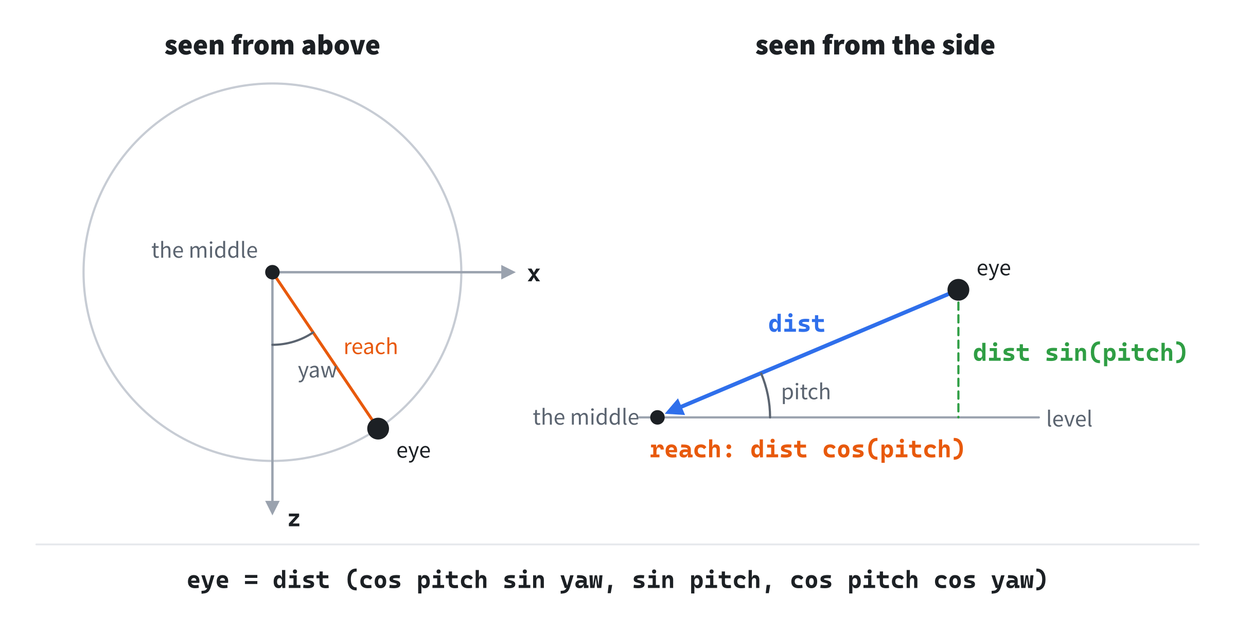
Seen from the side, the eye is dist from the middle, lifted by the pitch. So its height is dist sin(pitch), and its reach along the level is dist cos(pitch). Seen from above, that reach is turned from +z toward +x by the yaw. So the eye is at:
eye = dist (cos(pitch) sin(yaw), sin(pitch), cos(pitch) cos(yaw))That's Chapter 31's forward, starting from +z instead of -z, and scaled by the distance. Then lookAt from the eye to the middle builds the view. Dragging changes the yaw and the pitch, and the mouse's wheel changes the distance. So the wheel moves the eye nearer or farther, which is a dolly, not a zoom. A zoom would change the projection's field of view, as Chapter 30's did.
The pitch is limited to 1.4 radians either way, about 80 degrees. At the top of the sphere, the eye would look straight down at the middle, along the up hint, and Chapter 31's cross product would vanish. At 1.4, forward × up is still cos(1.4), 0.17, long.
Building Mesh Viewer
Mesh Viewer draws one mesh at a time in wireframe, turning slowly. Drag to orbit the camera, and roll the wheel to move it in and out. N shows the next mesh, Space stops the spin, and R puts the camera and the cube's turn back. The readout traces one corner through every step, with an amber dot at its pixel, and C moves on to the next corner.
Get the code. The complete project is in the
Mesh Viewerfolder of the book's repository.
Mesh Viewer starts from the skeleton, with its timing. It reads the mouse's movement and its wheel, but not its position. It reuses fillCircle from Chapter 3, fmt2 from Chapter 4 and setColor from Chapter 8. Its Vec2.h, Vec3.h and Mat4.h are Fly Camera's, and its Mesh.h is the one this chapter built. Its project copies pyramid.obj beside the program when it's built, as it does the font. Here are its includes and its colors:
#include <cmath>
#include <string>
#include <utility>
#include <vector>
#include "Vec2.h"
#include "Vec3.h"
#include "Mat4.h"
#include "Mesh.h"

constexpr int WINDOW_WIDTH  = 1000;
constexpr int WINDOW_HEIGHT = 700;

constexpr SDL_Color TEXT = { 235, 238, 242, 255 };
constexpr SDL_Color GREY = { 90, 100, 112, 255 };
constexpr SDL_Color AMBER = { 240, 200, 60, 255 };
The amber is for the traced corner. Then come the constants:
// The projection: the window's aspect, a field of view of 60 degrees, and
// the near and far planes. Then the mesh's spin, in radians a second, how
// far a drag turns the camera, in radians a pixel, and the camera's limits:
// its pitch, its distance from the middle, and the wheel's step.
constexpr float ASPECT = (float)WINDOW_WIDTH / (float)WINDOW_HEIGHT;
constexpr float FOV = 60.0f * PI / 180.0f;
constexpr float NEAR_DIST = 0.1f;
constexpr float FAR_DIST = 100.0f;
constexpr float SPIN_SPEED = 0.6f;
constexpr float DRAG_TURN = 0.01f;
constexpr float PITCH_LIMIT = 1.4f;
constexpr float MIN_DIST = 0.5f;
constexpr float MAX_DIST = 20.0f;
constexpr float WHEEL_STEP = 0.4f;
The projection's near plane is 0.1, and the camera can come as near as 0.5 to the middle. That's inside most of the meshes, which lets you see the clip at work. Each step of the wheel moves the camera 0.4. Then comes an edge:
// An edge of a mesh: its two corners, by index, the lower one first.
struct Edge
{
    int a;
    int b;
};
An edge is two corner numbers, kept with the lower first, so that the same edge always looks the same, whichever face it came from.
The Helpers
Four new functions go before main. The first makes a mesh's list of edges:
// A mesh's edges, each once. Each face's loop gives an edge from each
// corner to the next, and from its last corner back to its first. An edge
// shared by two faces comes up twice, and is kept the first time.
std::vector<Edge> edgesOf(const Mesh& m)
{
    std::vector<Edge> edges;
    for (const std::vector<int>& f : m.faces)
        for (size_t k = 0; k < f.size(); ++k)
        {
            int a = f[k];
            int b = f[(k + 1) % f.size()];
            if (a > b) std::swap(a, b);
            bool seen = false;
            for (const Edge& e : edges)
                if (e.a == a && e.b == b) seen = true;
            if (!seen) edges.push_back({ a, b });
        }
    return edges;
}
The % takes the last corner's edge back to the first. Each edge is swapped, if it needs to be, so that its lower corner comes first. Then it's kept only if it isn't in the list yet, which a search through the list finds out. For a mesh of a few dozen edges, the search is cheap, and it runs only when a mesh is chosen. The second is the clip:
// Clip an edge in clip space at the near plane, where z = -w. A point is
// beyond the plane when z + w is positive. An edge with both ends short of
// it is dropped, and one that crosses it has its short end moved to where
// z + w is 0. Before the divide, a straight edge is still a straight line
// in four coordinates, so the crossing is found as in Fly Camera.
bool clipAtNear(Vec4& a, Vec4& b)
{
    float da = a.z + a.w;
    float db = b.z + b.w;
    if (da < 0.0f && db < 0.0f) return false;
    if (da < 0.0f || db < 0.0f)
    {
        float t = da / (da - db);
        Vec4 onPlane = { a.x + (b.x - a.x) * t, a.y + (b.y - a.y) * t,
                         a.z + (b.z - a.z) * t, a.w + (b.w - a.w) * t };
        if (da < 0.0f) a = onPlane;
        else b = onPlane;
    }
    return true;
}
It's Fly Camera's clipNear, done in clip space, with z + w in place of the distance beyond the plane. The moved end is the mix of all four coordinates, since w changes along the edge too. Then a point in clip space is put on the window:
// A point in clip space, beyond the near plane, on the window: the divide
// by w, and the stretch across the window.
Vec2 toPixels(Vec4 c)
{
    return { (c.x / c.w * 0.5f + 0.5f) * WINDOW_WIDTH,
             (0.5f - c.y / c.w * 0.5f) * WINDOW_HEIGHT };
}
It's the divide and the viewport, and it's only called on a point beyond the near plane, whose w is positive. The last writes a Vec3 as text, for the readout:
// A Vec3 as text, such as (1.00, -0.50, 2.25).
std::string vecText(Vec3 v)
{
    return "(" + fmt2(v.x) + ", " + fmt2(v.y) + ", " + fmt2(v.z) + ")";
}
The readout uses it for the eye and for the traced corner's spaces.
The State
The state goes after the font is loaded. First come the meshes:
// The meshes: three built in, and a fourth from pyramid.obj, beside the
// program, if it's there and it loads. Then the edges of the one shown.
std::vector<Mesh> meshes = { builtinCube(), builtinOctahedron(),
                             builtinTetrahedron() };
Mesh loaded;
if (loadObj(folder + "pyramid.obj", loaded)) meshes.push_back(loaded);
int current = 0;
std::vector<Edge> edges = edgesOf(meshes[current]);
The file is looked for in the program's folder, from the skeleton's folder, as the font is. If it's missing or bad, the demo has three meshes instead of four. Then the camera and the rest:
// The orbit camera: its yaw and pitch about the middle, in radians, and
// its distance from it. Then the mesh's spin, whether it spins, whether
// the camera is being dragged, and the corner the readout traces.
float yaw = 0.6f;
float pitch = 0.4f;
float dist = 5.0f;
float spin = 0.0f;
bool spinning = true;
bool dragging = false;
int traced = 0;
The camera starts at a yaw of 0.6, a pitch of 0.4 and a distance of 5: the eye of the corner followed in One Corner, End to End. The projection never changes, so it's made once:
// The projection, which never changes.
Mat4 proj = Mat4::perspective(FOV, ASPECT, NEAR_DIST, FAR_DIST);
It's Chapter 30's perspective, with the constants' field of view and planes.
The Events
The keys choose the mesh and the corner, the drag orbits the camera, and the wheel moves it:
// Events: quitting, and the keys, clicks and turns of the wheel that
// happen once. A drag orbits the camera, and the wheel moves it
// nearer the middle or farther from it.
SDL_Event event;
while (SDL_PollEvent(&event))
{
    if (event.type == SDL_EVENT_QUIT) running = false;
    else if (event.type == SDL_EVENT_KEY_DOWN)
    {
        if (event.key.key == SDLK_ESCAPE) running = false;
        else if (event.key.key == SDLK_N)
        {
            current = (current + 1) % (int)meshes.size();
            edges = edgesOf(meshes[current]);
            traced = 0;
        }
        else if (event.key.key == SDLK_C)
            traced = (traced + 1) % (int)meshes[current].verts.size();
        else if (event.key.key == SDLK_SPACE) spinning = !spinning;
        else if (event.key.key == SDLK_R)
        {
            yaw = 0.6f;
            pitch = 0.4f;
            dist = 5.0f;
            spin = 0.0f;
        }
    }
    else if (event.type == SDL_EVENT_MOUSE_BUTTON_DOWN &&
             event.button.button == SDL_BUTTON_LEFT) dragging = true;
    else if (event.type == SDL_EVENT_MOUSE_BUTTON_UP) dragging = false;
    else if (event.type == SDL_EVENT_MOUSE_MOTION && dragging)
    {
        yaw -= event.motion.xrel * DRAG_TURN;
        pitch += event.motion.yrel * DRAG_TURN;
        pitch = SDL_clamp(pitch, -PITCH_LIMIT, PITCH_LIMIT);
    }
    else if (event.type == SDL_EVENT_MOUSE_WHEEL)
        dist = SDL_clamp(dist - event.wheel.y * WHEEL_STEP, MIN_DIST,
                         MAX_DIST);
}
In the preceding code, N moves on to the next mesh, wrapping round to the first, and makes its list of edges. It sets the traced corner back to 0, since the next mesh may have fewer corners. C moves on to the next corner. A drag turns the camera a hundredth of a radian a pixel. The yaw falls as the mouse moves right, so that the mesh seems to turn with the mouse. The wheel's y is how many steps it turned, positive away from you, which moves the camera in.
Each Frame's Work
Each frame, the mesh turns and its matrices are built:
// The mesh spins about y, and more slowly about x.
if (spinning) spin += SPIN_SPEED * dt;
Mat4 model = Mat4::rotationY(spin) * Mat4::rotationX(spin * 0.4f);
The turn about x is 0.4 of the turn about y, so that the mesh tumbles rather than only turning. Then the camera, and the one matrix:
// The eye sits on a sphere around the middle, at the camera's yaw,
// pitch and distance, and looks at the middle. Then one matrix does
// the model, the view and the projection.
Vec3 eye = { dist * std::cos(pitch) * std::sin(yaw),
             dist * std::sin(pitch),
             dist * std::cos(pitch) * std::cos(yaw) };
const Vec3 MIDDLE = { 0.0f, 0.0f, 0.0f };
const Vec3 UP = { 0.0f, 1.0f, 0.0f };
Mat4 view = Mat4::lookAt(eye, MIDDLE, UP);
Mat4 mvp = proj * view * model;
The eye is the last section's formula, and the view looks from it to the middle. Then mvp is the product of all three matrices, read from the right.
Drawing
After the skeleton clears the screen, every corner goes into clip space, once:
// Every corner, once: into clip space by the one matrix.
const Mesh& mesh = meshes[current];
std::vector<Vec4> clip(mesh.verts.size());
for (size_t i = 0; i < mesh.verts.size(); ++i)
    clip[i] = mvp.apply4(mesh.verts[i]);
The list holds a Vec4 for each corner, in the mesh's order, so that an edge finds its ends by their numbers. Then the edges:
// Every edge, once: clipped at the near plane, divided and put on the
// window. Its shade comes from its depth, w, against the middle's,
// which is the camera's distance: nearer edges are brighter. The
// edges drawn and the edges cut at the near plane are counted.
int drawn = 0;
int cut = 0;
for (const Edge& e : edges)
{
    Vec4 a = clip[e.a];
    Vec4 b = clip[e.b];
    bool whole = a.z + a.w >= 0.0f && b.z + b.w >= 0.0f;
    if (!clipAtNear(a, b)) continue;
    ++drawn;
    if (!whole) ++cut;
    float depth = (a.w + b.w) * 0.5f - dist;
    float shade = SDL_clamp(0.62f - depth * 0.22f, 0.3f, 1.0f);
    SDL_SetRenderDrawColor(renderer, (Uint8)(110 * shade),
                           (Uint8)(175 * shade), (Uint8)(240 * shade),
                           255);
    Vec2 pa = toPixels(a);
    Vec2 pb = toPixels(b);
    SDL_RenderLine(renderer, pa.x, pa.y, pb.x, pb.y);
}
In the preceding code, each edge's ends are copied, since the clip may move one. An edge with an end short of the near plane is counted as cut, if it survives the clip. Its shade comes from its depth: its ends' average w, less the camera's distance from the middle. An edge in front of the middle is brighter, and one behind it dimmer, which helps a wireframe read as solid. Then come the strips the readout and the controls sit on:
// Strips of the background's color for the readout and the controls,
// so that the mesh's edges don't show through the text.
SDL_SetRenderDrawColor(renderer, 24, 26, 30, 255);
SDL_FRect top = { 0.0f, 0.0f, (float)WINDOW_WIDTH, 124.0f };
SDL_FRect bottom = { 0.0f, WINDOW_HEIGHT - 36.0f, (float)WINDOW_WIDTH,
                     36.0f };
SDL_RenderFillRect(renderer, &top);
SDL_RenderFillRect(renderer, &bottom);
Then the readout's first three lines:
// The readout: the mesh, its counts, the eye, and the edges drawn.
drawText(renderer, font,
         mesh.name + ": " + std::to_string(mesh.verts.size()) +
         " corners, " + std::to_string(mesh.faces.size()) +
         " faces, " + std::to_string(edges.size()) + " edges",
         12, 10, TEXT);
drawText(renderer, font,
         "eye " + vecText(eye) + ", " + fmt2(dist) + " from the middle",
         12, 32, TEXT);
drawText(renderer, font,
         std::to_string(mesh.verts.size()) + " corners transformed, " +
         std::to_string(drawn) + " edges drawn, " +
         std::to_string(cut) + " cut", 12, 54, TEXT);
The third line shows the work: one transform for each corner, and the edges drawn and cut. Last comes the traced corner, and the controls:
// The traced corner, stage by stage: the model and the view take it
// to view space, and the projection to clip space. The divide gives
// NDC, and the stretch its pixel, where an amber dot marks it, unless
// it's short of the near plane.
Vec3 corner = mesh.verts[traced];
Vec3 inView = (view * model).apply(corner);
Vec4 c = proj.apply4(inView);
drawText(renderer, font,
         "corner " + std::to_string(traced) + " " + vecText(corner),
         560, 10, AMBER);
drawText(renderer, font, "view   " + vecText(inView), 560, 32, TEXT);
drawText(renderer, font,
         "clip   (" + fmt2(c.x) + ", " + fmt2(c.y) + ", " + fmt2(c.z) +
         ", " + fmt2(c.w) + ")", 560, 54, TEXT);
if (c.z + c.w >= 0.0f)
{
    Vec3 ndc = { c.x / c.w, c.y / c.w, c.z / c.w };
    Vec2 pixel = toPixels(c);
    drawText(renderer, font, "NDC    " + vecText(ndc), 560, 76, TEXT);
    drawText(renderer, font,
             "pixel  (" + std::to_string((int)std::lround(pixel.x)) +
             ", " + std::to_string((int)std::lround(pixel.y)) + ")",
             560, 98, TEXT);
    setColor(renderer, AMBER);
    fillCircle(renderer, pixel, 4.0f);
}
else
    drawText(renderer, font, "short of the near plane", 560, 76, TEXT);
drawText(renderer, font,
         "[Drag] orbit   [Wheel] in and out   [N] mesh   [C] corner   "
         "[Space] spin   [R] reset   [Esc] quit",
         12, WINDOW_HEIGHT - 26, GREY);
In the preceding code, the corner is traced step by step, so that each space can be shown. The model and the view take it to view space together, and then the projection takes it to clip space. If the corner is beyond the near plane, its NDC and its pixel are shown, and an amber dot marks it. Otherwise, it has no pixel. There's nothing to add to the skeleton's cleanup.
Trying It Out
Run the demo. The cube turns slowly, with its nearer edges brighter, and the readout traces corner 0. Then try it, step by step:
- Trace the worked corner. Press Space to stop the spin, then R, then C six times. The readout traces corner 6,
(1, 1, 1), to the pixel(547, 281). Its numbers are the ones One Corner, End to End worked out by hand. - Orbit. Drag across, and the camera swings around the cube, its yaw changing. Drag up and down, and it rises and falls, until the pitch stops it short of the top. The traced corner's view coordinates change as you go, but its own coordinates never do.
- Count the work. The third line says 8 corners are transformed and 12 edges drawn. Press N for the octahedron: 6 corners and 12 edges. Drawn by face loops, it would take 48 transforms and 24 lines.
- Go inside. Press N until the cube is back, and roll the wheel away from you until the camera is 0.5 from the middle. The camera is now inside the cube. The edges behind it are dropped, and the ones that pass it are cut at the near plane, and the readout counts them.
- Load the pyramid. Press N until the readout says
pyramid.obj. That mesh came from the file, centered and with its triangles turned round. Change a number in the copy of the file beside the program, and run the demo again. The shape changes, with no code changed.
The next image shows step 1.
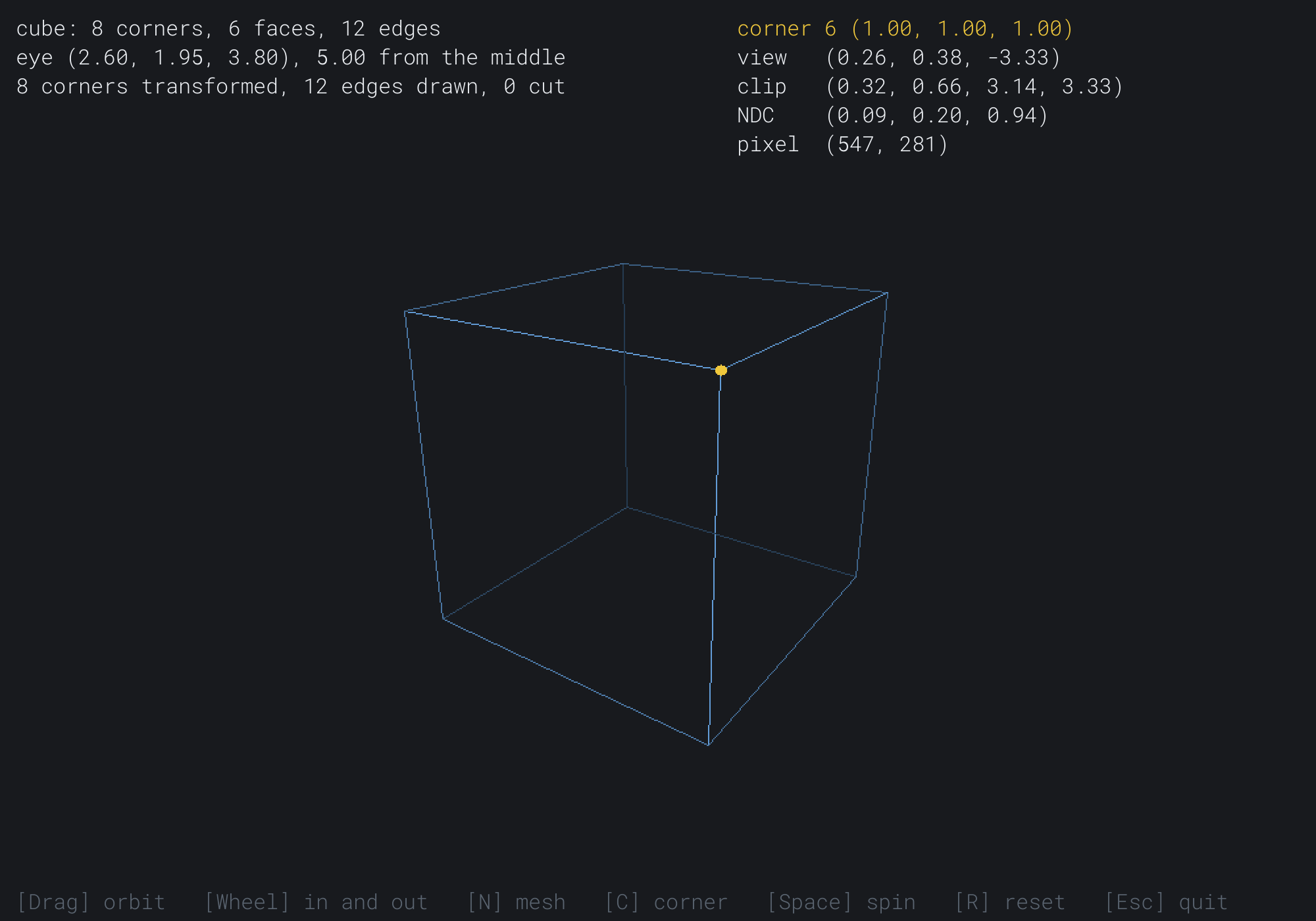
The amber dot is the cube's nearest corner, at the pixel that One Corner, End to End worked out by hand. The next image shows the pyramid from the file, turned and seen from higher up, with its top corner traced.
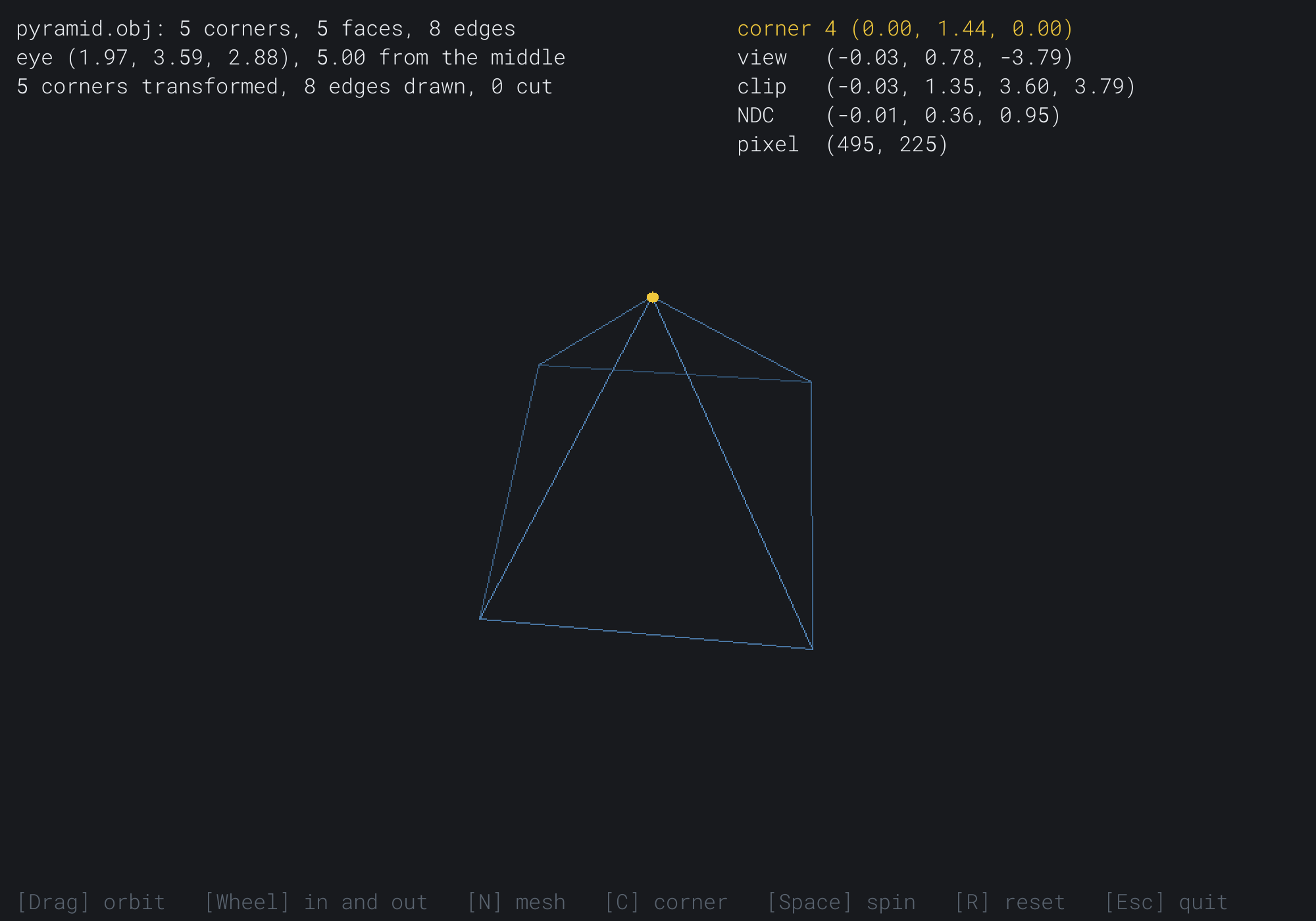
The top corner is (0.00, 1.44, 0.00), not 1.8 high as the file says, since the mesh was moved to center it. It's 3.79 in front of the eye, and near the top of the window's middle.
FAQ
Q) Why does my .obj file load inside out, or not at all?
A) Inside out usually means the faces are wound the other way round, which fixWinding can only mend for a convex mesh. A mesh with dents should keep the file's own winding, so take out the call. Not at all usually means the file has something this loader refuses: a corner number that names nothing, or a word that isn't a number. Some files from 3D tools also hold polygons whose corners don't lie flat, which a renderer should cut into triangles.
Q) My model is far too big, or far too small. Why?
A) An .obj file has no units, so one tool's model is 2 units across and another's is 2,000. The loader centers a mesh but doesn't size it. To show any model at the same size, find its farthest corner from the middle after centering. Then scale every corner so that the farthest is 1.5 away.
Q) Can the loader read texture coordinates and normals?
A) It can learn to. A vt line gives a texture coordinate and a vn line a normal, and a face's a/b/c gives each corner's three numbers. The loader skips both kinds of line, and reads only the first number. Chapter 34 keeps texture coordinates with each triangle, and Chapter 33 works out normals from the corners, so this book's meshes don't need them.
Exercises
The first three exercises need only a pencil. The others change Mesh Viewer.
- Trace a corner (paper). At the start, corner 0,
(-1, -1, -1), is at(-0.261, -0.380, -6.670)in view space. Find its clip coordinates, its NDC and its pixel, and check them against the readout. Press Space, then R, and it traces corner 0. - Count the work (paper). For the tetrahedron and the pyramid, how many transforms and lines a frame does drawing by face loops take? How many does Mesh Viewer's way take?
- Which way round (paper). On the cube in Figure 32.2, which face is the loop
0, 1, 2, 3? Is it counterclockwise from outside? - Your own mesh (code). Write an
.objfile by hand, such as a prism or a house, put it beside the program, and load it as a fifth mesh. - One size (code). Scale a loaded mesh, after centering, so that its farthest corner is 1.5 from the middle, as the FAQ describes.
- All six planes (challenge). Clip against the far plane and the four sides too, in clip space: z at most w, and x and y between -w and w. Each test has its own distance, such as w - z for the far plane, and the same t. Count the edges cut by each plane.
For the code exercises, work on a copy of the demo's folder, so that the original stays as the chapter describes it.
AI Exercise (Optional)
A mesh needn't come from a file. With an AI's help, you can make them from code, in any detail you like. Open your AI chatbot of choice, and try a prompt like this:
"I have a C++ demo using SDL3 that draws meshes in wireframe. A mesh is a struct with a std::string name, a std::vector<Vec3> verts of corners, and a std::vector<std::vector<int>> faces, each face a loop of indices into the corners, counterclockwise as seen from outside. Please write functions that build meshes from code: a sphere from rings and slices, a torus from a ring around a ring, and a cylinder with its two end caps, each with a detail number that sets how many rings and slices it has. Keep every face counterclockwise from outside, and make the sphere's top and bottom from triangles. Then add keys that raise and lower the detail of the mesh being shown. Explain how you made sure each face is wound the right way, and why a torus can't be checked by comparing each face with the mesh's center."
That prompt describes the mesh you built, so the AI builds on it, rather than writing its own. A torus has a hole, so its center isn't inside it, and Mesh Viewer's fixWinding would turn its inner faces wrongly. That's why each face has to be wound the right way as it's made.
Then make a spiral staircase, or a twisted tower, by turning each ring of a cylinder a little more than the one below.
Summary
The pipeline takes a corner through five steps: the model matrix, the view matrix, the projection, the divide by w and the viewport. The first three multiply into one matrix, P V M, built once a frame, so each corner costs one apply4. That one matrix leaves the corners in clip space, so the near clip happens there: a point is beyond the near plane when z + w is at least 0, and an edge crosses it where that's 0. A mesh is a list of corners and a list of faces, each a loop of corner numbers wound counterclockwise from outside. Transforming each corner once and drawing each edge once saves most of the work that drawing face by face repeats. An .obj file holds corners and faces as text, and a loader must refuse a bad file rather than crash. It centers the mesh, and turns any face whose normal points toward the center. The orbit camera's eye sits on a sphere, at a yaw, a pitch and a distance, looking at the middle. Chapter 33 fills the faces, and has to decide which of them hide which.