
Chapter 24 laid a texture on a flat quad, with SDL_RenderGeometry blending each corner's texture coordinate across it. Chapter 33 filled triangles itself, a pixel at a time, with a depth for each pixel. This chapter puts the two together, and lays a texture on every face of a turning cube, through Chapter 33's rasterizer.
Most of it is what you'd expect. Each corner gets a texture coordinate, and Chapter 33's weights blend them across each triangle. One thing isn't. Blended straight across the picture, as depth was, texture coordinates come out wrong on any surface seen at a slant, and the checks of a checkerboard bend. The fix blends them over w, and divides, and it's called perspective-correct interpolation. The demo shows both, and measures how far apart they are.
In this chapter, we will:
- Give each corner of each face its own texture coordinate
- Blend texture coordinates across a triangle with Chapter 33's weights
- See why a straight blend across the picture is wrong for a surface at a slant
- Blend them over w and divide, so that they come out right
- See why depth never needed that fix
- Build Textured Cube, a checkered cube with a key that switches the two blends
We'll start with the corners.
Texture Coordinates in 3D
A Coordinate for Each Corner of Each Face
Chapter 24 gave each corner of a quad a texture coordinate, a UV, that says where in the texture that corner samples. A cube's faces need the same, but a cube's corner is shared by three faces, and each face wants a different UV there. The corner at the cube's top front right is the top right of the front face, the top left of the right face and the bottom right of the top face. So the cube's 8 corners become 24 pairs of a corner and a UV, 4 for each face.
That's why a UV belongs to a face's corner, not to a mesh's corner, and why Chapter 32's Mesh doesn't store them. It's also why an .obj file lists its texture coordinates on vt lines of their own, and a face names each corner's position and UV separately, as a/b. Textured Cube gives the UVs to the cube's triangles, after it fans each face. Chapter 32 built every face's loop starting at its bottom left corner, as seen from outside, and running counterclockwise. So the four corners get the UVs (0, 1), (1, 1), (1, 0) and (0, 0), since v grows down an SDL texture. The texture then sits upright on each side.
Blending Them
Inside a triangle, Chapter 33's weights blend the UVs, as they blended depth:
u = b0 u0 + b1 u1 + b2 u2
v = b0 v0 + b1 v1 + b2 v2
Take the weights 0.2, 0.3 and 0.5, and the UVs (0, 0), (1, 0) and (0, 1). The pixel samples the texture at (0.3, 0.5). That's called affine interpolation, a straight-line blend across the picture. It's how SDL_RenderGeometry blends, and it's what Chapter 24's flat quad needed. On a surface seen at a slant, it's wrong.
Affine and Perspective-Correct
Equal Steps on the Picture
The trouble is the divide. A surface running away from the eye is squeezed by the divide, more the farther it is. So equal steps across the picture aren't equal steps along the surface. The next image shows a segment running from a depth of 1 to a depth of 3, with its u marked from 0 to 1.
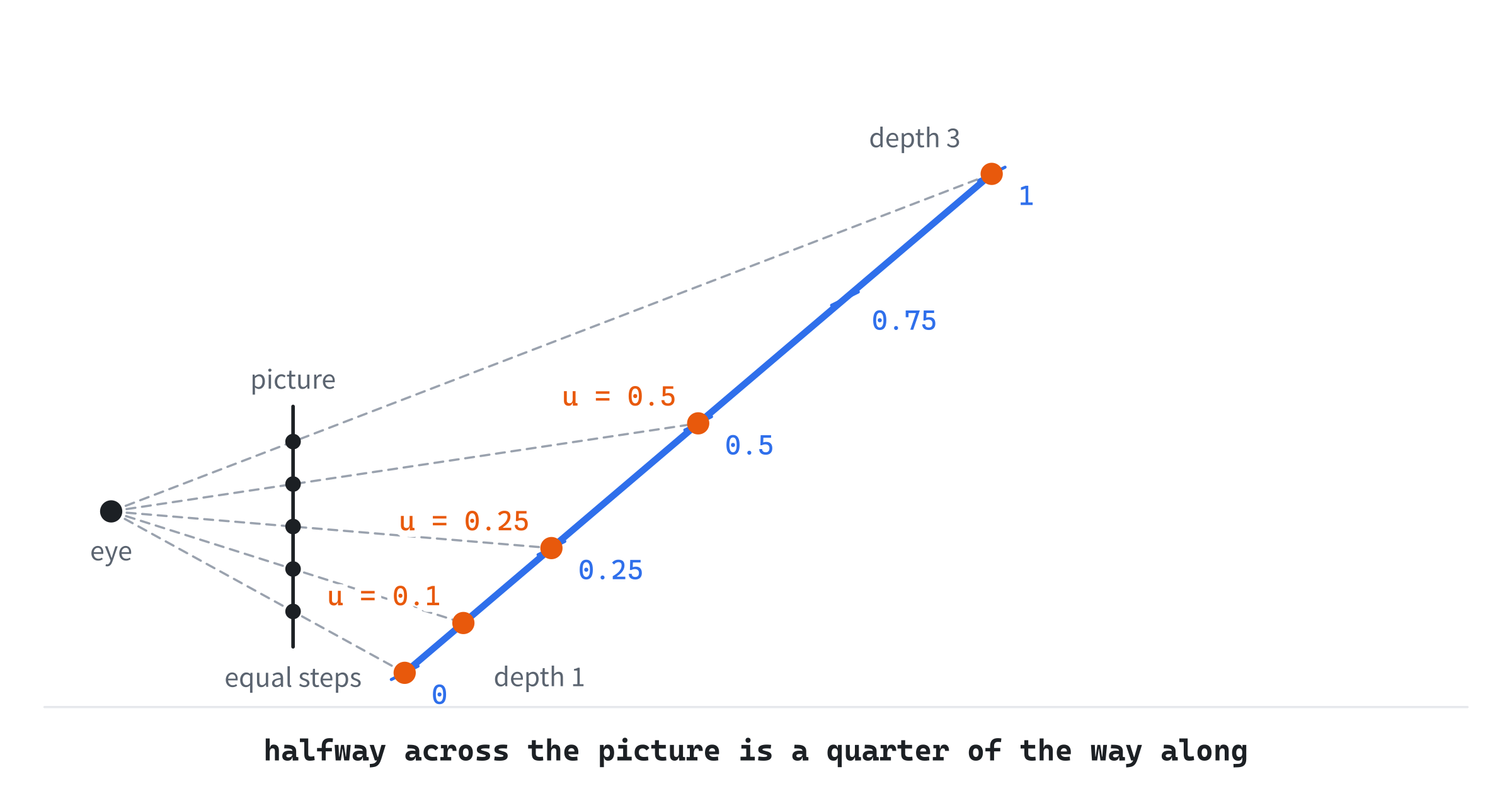
Rays through five equal steps on the picture land at u = 0, 0.1, 0.25, 0.5 and 1. Halfway across the picture, the true u is 0.25, but a straight blend says 0.5. So the near half of the segment's picture shows only a quarter of the texture, and a straight blend shows half. The far end, squeezed into few pixels, holds most of the texture.
What Affine Does to a Square
A cube's face is two triangles, and affine interpolation blends each on its own. The next image shows a checkered square tilted away, with its two triangles, drawn both ways.
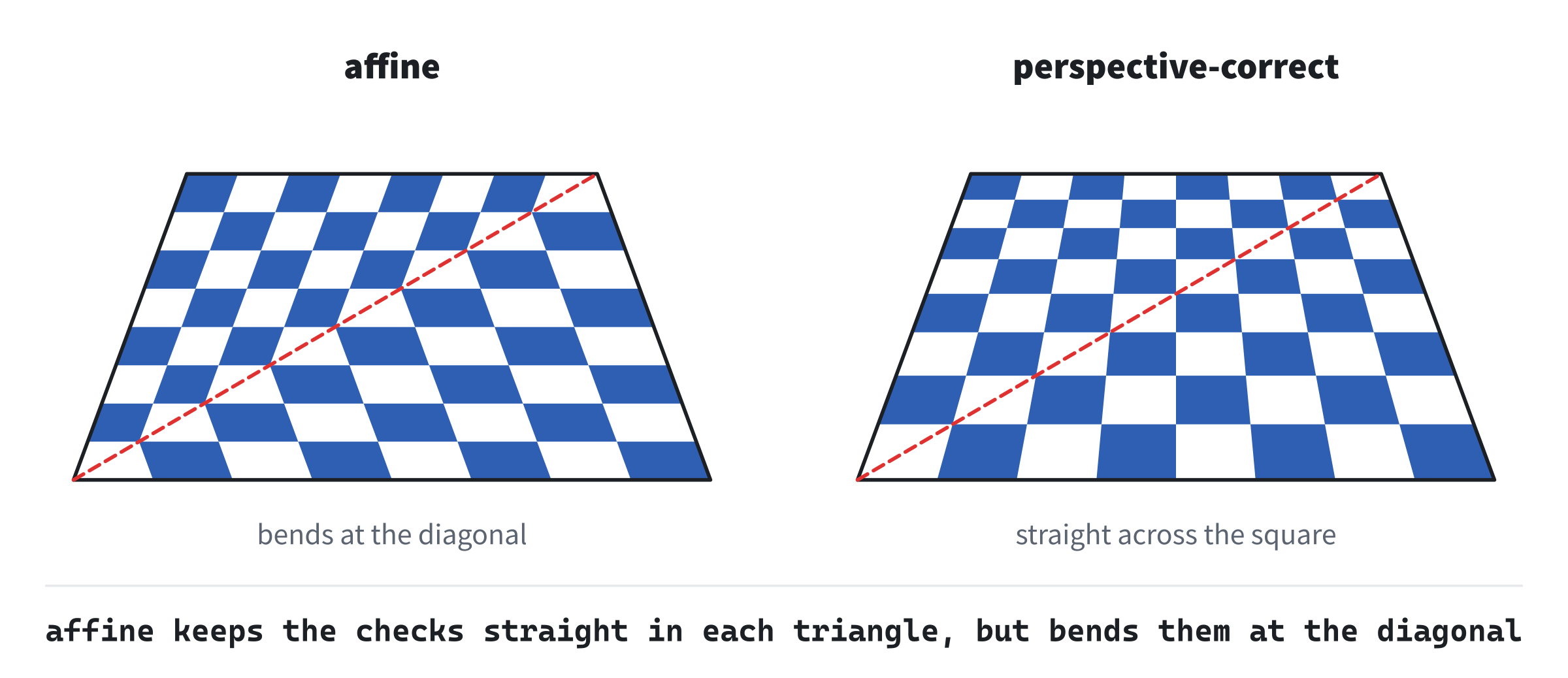
Within each triangle, affine interpolation keeps the checks' lines straight and evenly spaced, as a straight blend must. But the two triangles disagree along the diagonal they share, so the lines bend there. The checks don't crowd toward the far edge, as they should. It's Chapter 24's crease, but caused by depth now, not by a quad that isn't a parallelogram.
The error grows with how much the depth changes across a triangle. Halfway along an edge whose ends' depths differ by a ratio r, the straight blend is off by (r - 1) / (2 (r + 1)) of the texture. For a ratio of 1.1, that's 0.024. For a ratio of 3, as in the segment above, it's 0.25. So small triangles, each nearly at one depth, hide the error, and game consoles of the 1990s that blended straight cut big triangles into small ones.
Blending Over w
The fix comes from Chapter 33, which found that 1 over w is a straight-line function of the place on the picture, for any flat triangle. A texture coordinate is a straight-line function of the place on the face, in 3D: u = α x + β y + γ z + δ, for some numbers. Divide that by w. Then x / w and y / w are the place on the picture, and z / w is -1. And δ / w is a straight-line function of the picture's place, as 1 over w is. So u over w is a straight-line function of the place on the picture too.
So the right way to blend is to blend u over w and 1 over w straight, which is exact, and then divide one by the other to get u back:
u = (b0 u0 / w0 + b1 u1 / w1 + b2 u2 / w2) / (b0 / w0 + b1 / w1 + b2 / w2)That's perspective-correct interpolation. For the segment, halfway across the picture, the two blends are:
u / w = (0 / 1 + 1 / 3) / 2 = 1/6
1 / w = (1 / 1 + 1 / 3) / 2 = 2/3
Divided, u is 0.25, exactly where the ray lands. It costs a division at every pixel, which is why early hardware skipped it.
Why Depth Needed No Fix
Chapter 33 blended depth straight across the picture, and that was exact. The depth it blended was NDC's z, which is already -A + B / w: a straight-line function of 1 over w. View space's depth, w itself, would have needed the same fix as u.
Why Our Own Rasterizer
The SDL_RenderGeometry function takes each corner as a position on the screen, a color and a UV. It has no w, so it can only blend the UV straight, and it can't do perspective-correct interpolation. That's why Textured Cube draws through Chapter 33's rasterizer. A graphics card's 3D pipeline keeps w for every corner, and blends perspective-correctly as a matter of course.
Building Textured Cube
Textured Cube draws a cube 2.6 units on a side, with an 8 by 8 checkerboard on every face, turning under a light. T switches between affine and perspective-correct interpolation, and the readout says how far apart the two are. Drag to orbit the camera, roll the wheel to move it in and out, Space stops the spin, and R puts everything else back.
Get the code. The complete project is in the
Textured Cubefolder of the book's repository.
Textured Cube starts from the skeleton, with its timing. It reads the mouse's movement and its wheel, but not its position. It reuses fmt2 from Chapter 4 and toPixels from Chapter 33. Its Vec2.h, Vec3.h, Mat4.h and Mesh.h are Solid Cube's. Here are its includes and its colors:
#include <algorithm>
#include <cmath>
#include <string>
#include <vector>
#include "Vec2.h"
#include "Vec3.h"
#include "Mat4.h"
#include "Mesh.h"

constexpr int WINDOW_WIDTH  = 1000;
constexpr int WINDOW_HEIGHT = 700;

constexpr SDL_Color TEXT = { 235, 238, 242, 255 };
constexpr SDL_Color GREY = { 90, 100, 112, 255 };
Then come the picture's size and the constants:
// The picture the rasterizer fills: a pixel for each of the window's.
constexpr int PIC_WIDTH = WINDOW_WIDTH;
constexpr int PIC_HEIGHT = WINDOW_HEIGHT;

// The projection, the spin and the orbit camera, as in Solid Cube, with
// the camera allowed a little nearer.
constexpr float ASPECT = (float)WINDOW_WIDTH / (float)WINDOW_HEIGHT;
constexpr float FOV = 55.0f * PI / 180.0f;
constexpr float NEAR_DIST = 0.1f;
constexpr float FAR_DIST = 100.0f;
constexpr float SPIN_SPEED = 0.5f;
constexpr float DRAG_TURN = 0.01f;
constexpr float PITCH_LIMIT = 1.4f;
constexpr float MIN_DIST = 2.4f;
constexpr float MAX_DIST = 12.0f;
constexpr float WHEEL_STEP = 0.4f;
They're Solid Cube's, but the camera can come as near as 2.4, close to the cube's corners. It goes out only to 12, in steps of 0.4. Then the texture's:
// The texture: a checkerboard of 8 by 8, light and blue, with a red stripe
// along its left edge and its top, so that its way round shows.
constexpr int CHECKS = 8;
constexpr SDL_Color LIGHT_CHECK = { 235, 235, 240, 255 };
constexpr SDL_Color DARK_CHECK = { 45, 100, 195, 255 };
constexpr SDL_Color STRIPE = { 220, 70, 60, 255 };
A checkerboard is the best texture for showing the blend, since any bend in its straight lines shows at once. The stripe on two edges shows which way up the texture is. Then the cube's triangles:
// A triangle of the cube, in its own space, with a texture coordinate at
// each corner.
struct TexTri
{
    Vec3 p[3];
    Vec2 uv[3];
};
Each corner has its position and its UV. On the picture, a corner carries more:
// A corner on the picture: its pixel, its depth in NDC, 1 over its w, and
// its texture coordinate.
struct TexVert
{
    Vec2 p;
    float z;
    float invW;
    Vec2 uv;
};
Its 1 over w is worked out once, when the corner is projected, so that the fill needn't divide by w for every pixel. Then a triangle ready to fill:
// A triangle ready to fill: its corners on the picture, and its brightness.
struct TexDraw
{
    TexVert v[3];
    float bright;
};
It carries a brightness rather than a color, since the color comes from the texture at each pixel.
The Helpers
Four new functions go before main. The first is the texture itself:
// The texture, made by a function of u and v rather than stored. Both are
// clamped first, since a blend at a triangle's edge can come out a hair
// outside 0 to 1, and the 8 by 8 checks come from their whole parts.
SDL_Color sampleChecker(Vec2 uv)
{
    float u = SDL_clamp(uv.x, 0.0f, 0.999f);
    float v = SDL_clamp(uv.y, 0.0f, 0.999f);
    if (u < 0.06f || v < 0.06f) return STRIPE;
    bool light = ((int)(u * CHECKS) + (int)(v * CHECKS)) % 2 == 1;
    return light ? LIGHT_CHECK : DARK_CHECK;
}
A texture is a rule that turns a texture coordinate into a color, and this one is a function, rather than an image in memory. Its u and v are clamped, since a blend right at a triangle's edge can come out a hair outside 0 to 1, from rounding. Each is then multiplied by 8, and the whole parts give the check's column and row. When their sum is odd, the check is light. The stripe covers the first 6 percent of u and of v. The second makes the cube's triangles:
// The cube's textured triangles: each face of the built-in cube, scaled,
// with the texture's corners on its corners, cut into a fan of two
// triangles that carry their corners' texture coordinates. Each face's
// loop starts at its bottom left corner, seen from outside, and v grows
// down the texture, as SDL's does.
std::vector<TexTri> texturedCube(float size)
{
    const Vec2 FACE_UV[4] = { { 0, 1 }, { 1, 1 }, { 1, 0 }, { 0, 0 } };
    Mesh cube = builtinCube();
    std::vector<TexTri> tris;
    for (const std::vector<int>& f : cube.faces)
        for (int k = 1; k + 1 < (int)f.size(); ++k)
        {
            const int corner[3] = { 0, k, k + 1 };
            TexTri t;
            for (int i = 0; i < 3; ++i)
            {
                t.p[i] = cube.verts[f[corner[i]]] * size;
                t.uv[i] = FACE_UV[corner[i]];
            }
            tris.push_back(t);
        }
    return tris;
}
In the preceding code, FACE_UV holds the UVs of a face's four corners, in its loop's order. The fan is Solid Cube's, with each triangle's three corners taken from the face's corners 0, k and k + 1. Each corner of the triangle gets its position from the mesh, scaled, and its UV from FACE_UV, by its place in the face. So each of the cube's 12 triangles carries its own three UVs. The third puts a triangle's corners on the picture:
// A triangle's corners onto the picture, through clip space, each with
// its NDC depth, 1 over its w and its texture coordinate. A triangle with
// a corner short of the near plane gives false, to be dropped whole.
bool toPicture(const Mat4& toClip, const Vec3 corner[3], const Vec2 uv[3],
               TexDraw& d)
{
    for (int k = 0; k < 3; ++k)
    {
        Vec4 c = toClip.apply4(corner[k]);
        if (c.z + c.w < 0.0f) return false;
        d.v[k] = { toPixels(c), c.z / c.w, 1.0f / c.w, uv[k] };
    }
    return true;
}
It's Solid Cube's toPicture, with each corner's 1 over w and UV added, and without a depth for sorting. The fourth fills the triangle:
// Fill a textured triangle into the picture, with the z-buffer, by Solid
// Cube's cross products. Over the area, they're the weights b0, b1 and b2.
// Each pixel's texture coordinate is blended two ways: affine, from the
// corners' coordinates, and perspective-correct, from their coordinates
// over w and their 1 over w, then divided. The texture is sampled at the
// one asked for, and the largest gap between the two is kept in worst.
void fillTextured(std::vector<SDL_Color>& color, std::vector<float>& depth,
                  const TexDraw& d, bool perspective, float& worst)
{
    const TexVert& v0 = d.v[0];
    const TexVert& v1 = d.v[1];
    const TexVert& v2 = d.v[2];
    float area = (v1.p - v0.p).cross(v2.p - v0.p);
    if (std::fabs(area) < 1e-6f) return;

    // The box of pixels the triangle covers, kept inside the picture.
    int x0 = std::max(0, (int)std::floor(std::min({ v0.p.x, v1.p.x, v2.p.x })));
    int x1 = std::min(PIC_WIDTH - 1,
                      (int)std::ceil(std::max({ v0.p.x, v1.p.x, v2.p.x })));
    int y0 = std::max(0, (int)std::floor(std::min({ v0.p.y, v1.p.y, v2.p.y })));
    int y1 = std::min(PIC_HEIGHT - 1,
                      (int)std::ceil(std::max({ v0.p.y, v1.p.y, v2.p.y })));
    for (int y = y0; y <= y1; ++y)
        for (int x = x0; x <= x1; ++x)
        {
            Vec2 p = { x + 0.5f, y + 0.5f };
            float e0 = (v2.p - v1.p).cross(p - v1.p);
            float e1 = (v0.p - v2.p).cross(p - v2.p);
            float e2 = (v1.p - v0.p).cross(p - v0.p);
            bool inside = (e0 >= 0 && e1 >= 0 && e2 >= 0) ||
                          (e0 <= 0 && e1 <= 0 && e2 <= 0);
            if (!inside) continue;
            float b0 = e0 / area;
            float b1 = e1 / area;
            float b2 = e2 / area;
            float z = b0 * v0.z + b1 * v1.z + b2 * v2.z;
            int i = y * PIC_WIDTH + x;
            if (z >= depth[i]) continue;

            Vec2 affine = v0.uv * b0 + v1.uv * b1 + v2.uv * b2;
            float invW = b0 * v0.invW + b1 * v1.invW + b2 * v2.invW;
            Vec2 correct = (v0.uv * (b0 * v0.invW) + v1.uv * (b1 * v1.invW) +
                            v2.uv * (b2 * v2.invW)) / invW;
            worst = std::max(worst, (correct - affine).length());
            SDL_Color texel = sampleChecker(perspective ? correct : affine);
            depth[i] = z;
            color[i] = { (Uint8)(texel.r * d.bright),
                         (Uint8)(texel.g * d.bright),
                         (Uint8)(texel.b * d.bright), 255 };
        }
}
In the preceding code, the cross products e0, e1 and e2 are Solid Cube's. Divided by the area, they're the weights. The depth test comes first, before any work on the texture, so that a pixel that's hidden costs nothing more. Then the UV is blended both ways. The affine blend weights the corners' UVs. The perspective-correct blend weights each corner's UV times its 1 over w, and divides by the weighted 1 over w. The distance between the two blends is kept in worst, if it's the largest yet. The texture is sampled at the UV asked for, and the texel is scaled by the triangle's brightness.
The State
The state goes after the font is loaded. The picture, its texture and its depths come first, made exactly as in Solid Cube. Then the cube and the controls:
// The cube, 2.6 units on a side, made once. Then the light's direction,
// and the controls: the texture coordinates' blend, the spin and the
// orbit camera.
std::vector<TexTri> cube = texturedCube(1.3f);
const Vec3 LIGHT = Vec3(-0.35f, 0.7f, 0.6f).normalized();
bool perspective = true;
float spin = 0.0f;
bool spinning = true;
bool dragging = false;
float yaw = 0.5f;
float pitch = 0.35f;
float dist = 5.0f;
The cube is made once, from the built-in cube scaled by 1.3. The demo starts perspective-correct. Then the projection:
// The projection, which never changes.
Mat4 proj = Mat4::perspective(FOV, ASPECT, NEAR_DIST, FAR_DIST);
It's Solid Cube's projection, at 55 degrees.
The Events
T switches the blend, and the rest are Solid Cube's:
// Events: quitting, and the keys, clicks and turns of the wheel that
// happen once. A drag orbits the camera, and the wheel moves it.
SDL_Event event;
while (SDL_PollEvent(&event))
{
    if (event.type == SDL_EVENT_QUIT) running = false;
    else if (event.type == SDL_EVENT_KEY_DOWN)
    {
        if (event.key.key == SDLK_ESCAPE) running = false;
        else if (event.key.key == SDLK_T) perspective = !perspective;
        else if (event.key.key == SDLK_SPACE) spinning = !spinning;
        else if (event.key.key == SDLK_R)
        {
            perspective = true;
            spin = 0.0f;
            yaw = 0.5f;
            pitch = 0.35f;
            dist = 5.0f;
        }
    }
    else if (event.type == SDL_EVENT_MOUSE_BUTTON_DOWN &&
             event.button.button == SDL_BUTTON_LEFT) dragging = true;
    else if (event.type == SDL_EVENT_MOUSE_BUTTON_UP) dragging = false;
    else if (event.type == SDL_EVENT_MOUSE_MOTION && dragging)
    {
        yaw -= event.motion.xrel * DRAG_TURN;
        pitch += event.motion.yrel * DRAG_TURN;
        pitch = SDL_clamp(pitch, -PITCH_LIMIT, PITCH_LIMIT);
    }
    else if (event.type == SDL_EVENT_MOUSE_WHEEL)
        dist = SDL_clamp(dist - event.wheel.y * WHEEL_STEP, MIN_DIST,
                         MAX_DIST);
}
In the preceding code, R puts the blend back to perspective-correct, as well as the spin and the camera.
Each Frame's Work
Each frame, the cube turns, and the camera's matrices are built, as in Solid Cube:
// The cube spins, and the eye orbits the middle, as in Solid Cube.
if (spinning) spin += SPIN_SPEED * dt;
Mat4 model = Mat4::rotationY(spin) * Mat4::rotationX(spin * 0.5f);
Vec3 eye = { dist * std::cos(pitch) * std::sin(yaw),
             dist * std::sin(pitch),
             dist * std::cos(pitch) * std::cos(yaw) };
const Vec3 MIDDLE = { 0.0f, 0.0f, 0.0f };
const Vec3 UP = { 0.0f, 1.0f, 0.0f };
Mat4 toClip = proj * Mat4::lookAt(eye, MIDDLE, UP);
The model matrix stays separate, since culling and lighting happen in the world.
Drawing
After the skeleton clears the screen, the picture is cleared as in Solid Cube, and each triangle is drawn:
// Each triangle: into the world, culled if it faces away, lit, put
// on the picture with its texture coordinates, and filled.
float worst = 0.0f;
for (const TexTri& t : cube)
{
    Vec3 world[3] = { model.apply(t.p[0]), model.apply(t.p[1]),
                      model.apply(t.p[2]) };
    Vec3 n = (world[1] - world[0]).cross(world[2] - world[0])
                 .normalized();
    Vec3 center = (world[0] + world[1] + world[2]) / 3.0f;
    if (n.dot(eye - center) <= 0.0f) continue;
    TexDraw d;
    d.bright = SDL_clamp(n.dot(LIGHT), 0.0f, 1.0f) * 0.7f + 0.3f;
    if (!toPicture(toClip, world, t.uv, d)) continue;
    fillTextured(color, depth, d, perspective, worst);
}
The triangle's corners go into the world, where its normal culls it and Lambert's law lights it, as in Solid Cube. Its floor is 0.3, so that a face turned from the light is still seen. The triangle needs no painter's algorithm, since the z-buffer is always on. The variable is named world, not w, since w means the fourth coordinate in this chapter. Then the picture is shown as in Solid Cube, on strips like Camera's, and the readout goes on top:
// The readout: the blend in use, and the largest gap between the two
// blends on any pixel drawn, as a share of the texture's width.
drawText(renderer, font,
         std::string("texture coordinates: ") +
         (perspective ? "perspective-correct" : "affine"),
         12, 10, TEXT);
drawText(renderer, font,
         "the two blends differ by up to " + fmt2(worst) +
         " of the texture", 12, 32, TEXT);
drawText(renderer, font,
         "[T] affine or correct   [Space] spin   [Drag] orbit   "
         "[Wheel] in and out   [R] reset   [Esc] quit",
         12, WINDOW_HEIGHT - 26, GREY);
The gap is the largest distance between the two blends' UVs on any pixel drawn this frame, measured in the texture's width. A gap of 0.125 is a whole check. The cleanup destroys the texture first, as Solid Cube's does.
Trying It Out
Run the demo. The cube turns, with its checks lying flat on each face, their lines straight and crowding a little toward each face's far edge. Then try it, step by step:
- Switch to affine. Press T. On each face turned at a slant, the checks' lines bend along one diagonal. That's the line between the face's two triangles. Press T again, and they straighten.
- Read the gap. Press Space to stop the spin. The readout says how far the two blends are apart. At the start, it's about 0.2 of the texture, more than a check and a half.
- Turn a face to you. Drag until one face is square on. On that face, the two blends agree, since its corners are all at nearly the same depth. Turn it away, and the gap grows.
- Come closer. Press R, to come back to the start's view. Then roll the wheel away from you to bring the camera in. The nearer it is, the more the depth changes across each face, and the bigger the gap: about 0.67 of the texture at 2.4 units out. From 12 units out, it's only 0.07, about half a check, and affine looks almost right.
The next image shows the start, perspective-correct.
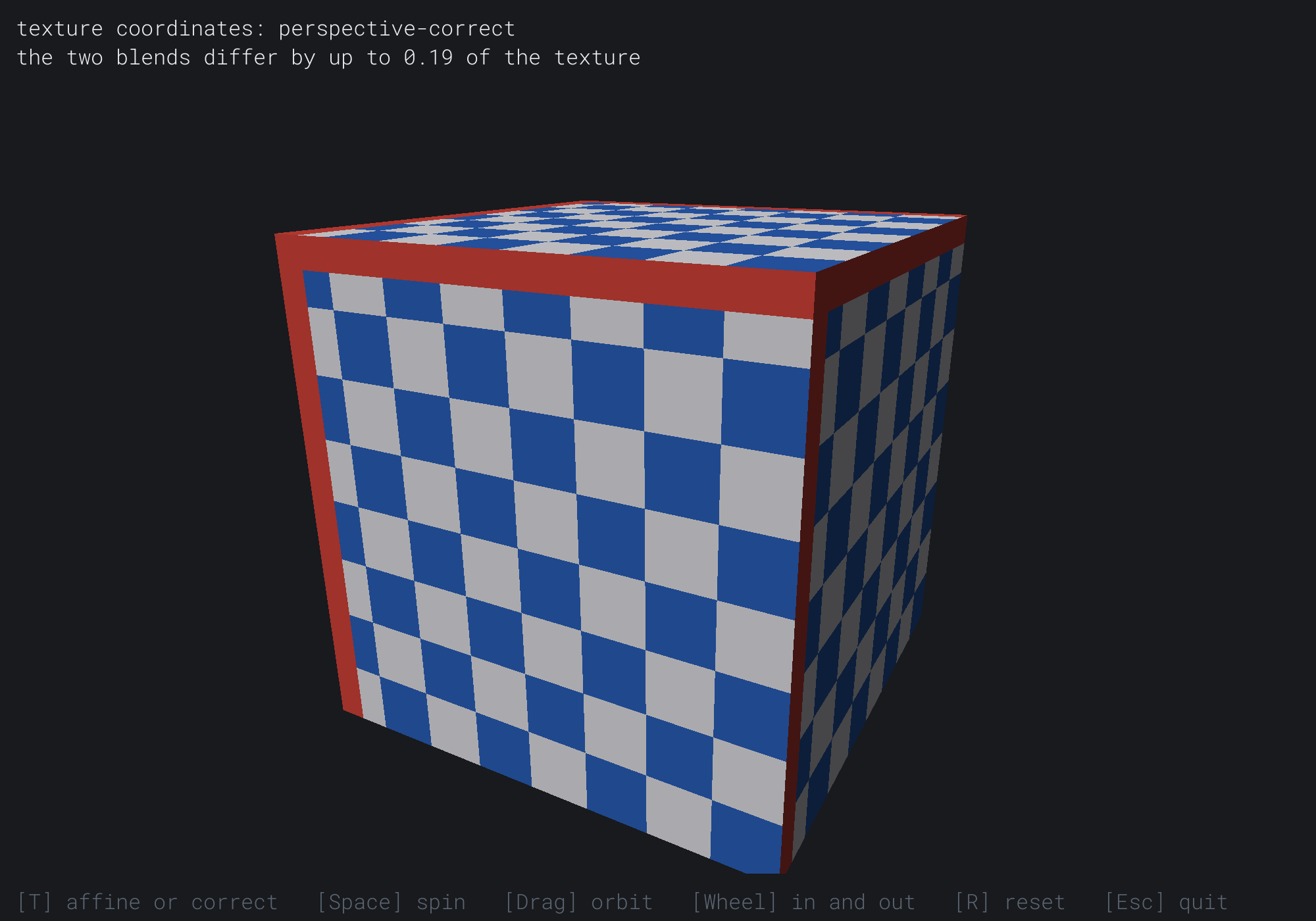
The checks' lines run straight across each face, from one edge to the other, through the diagonal no one can see. The next image shows the same view, affine.
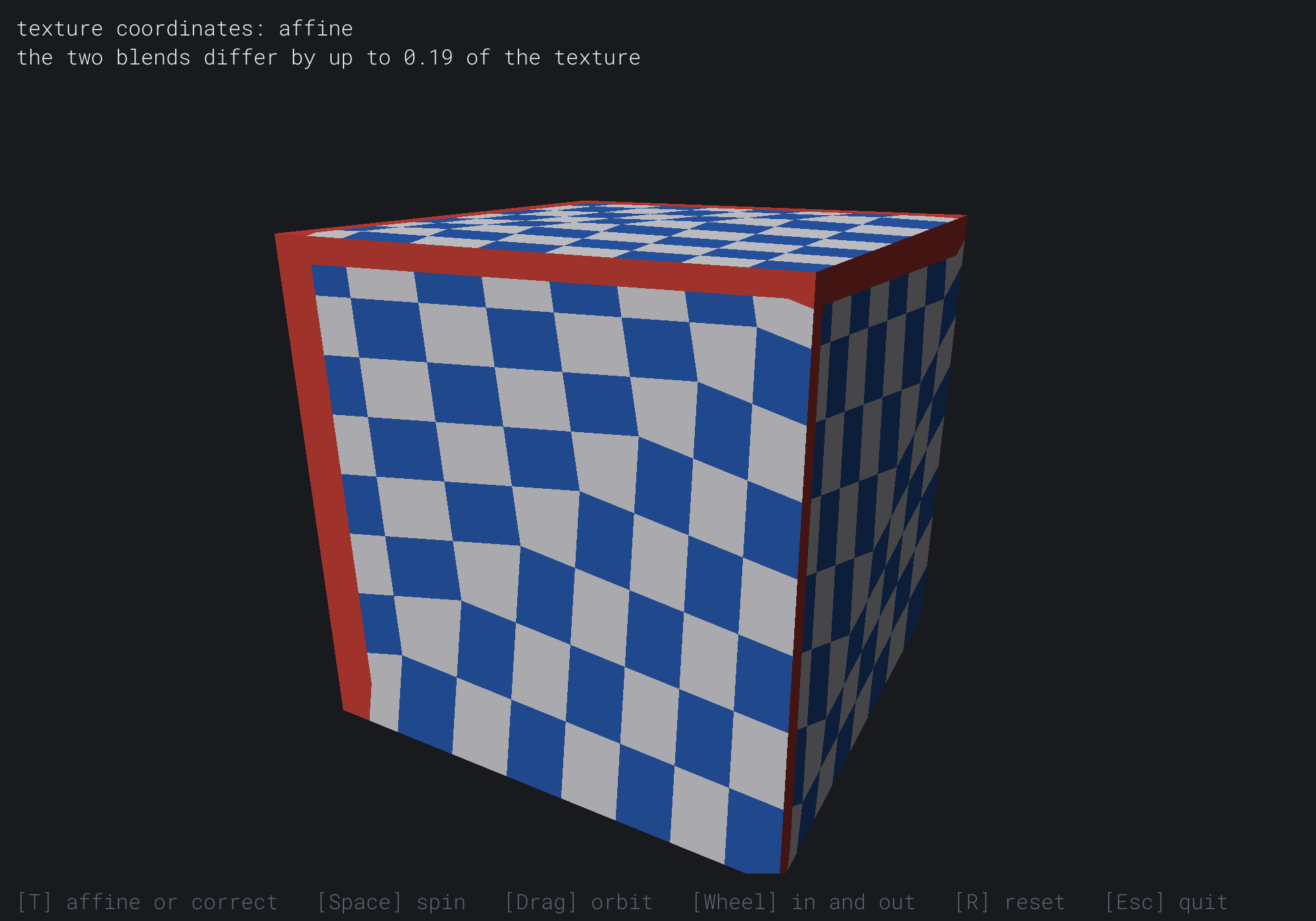
The front face's lines bend along the diagonal from its top right to its bottom left, and its checks are even, rather than crowding toward the far edge. The readout says the two blends differ by up to 0.19 of the texture.
Two Corners We Cut
Textured Cube leaves two things simpler than a game would. The first is the light. It multiplies each texel's stored color by the brightness, but stored colors are gamma-encoded: their numbers grow more slowly than the light they stand for, to spend more of the 256 levels on dark colors, which eyes tell apart better. Light adds up in the light's own measure, so a game turns each stored color into light, multiplies, and turns it back. Done that way, a brightness of 0.3 leaves a color at 0.58 of its stored value, not 0.3, nearly twice as bright.
The second is sampling. Each pixel samples the texture once, at its center, and there are no mipmaps. A face seen edge on squeezes many checks into each pixel, so its checks flicker as it turns. Chapter 24's mipmaps are the cure, and a graphics card blends between them for every pixel.
FAQ
Q) Could I cut the triangles small and keep SDL_RenderGeometry?
A) It would help, since small triangles each sit at nearly one depth, and the error shrinks with the depth's change across each. But it never goes away, and every cut costs triangles. A graphics card's own 3D pipeline blends perspective-correctly, which is the real answer.
Q) What about a corner behind the camera?
A) Its w is negative, so 1 over w changes sign, and the blend of 1 over w passes through 0 inside the triangle, where the divide fails. That's why toPicture drops any triangle with a corner short of the near plane. A renderer that lets the camera come close clips the triangle at the near plane instead, as Chapter 32 clipped edges.
Q) Does every pixel really need a division?
A) Perspective-correct interpolation needs one for each pixel's u, v pair. Software renderers in the 1990s divided only every 16 pixels along a row, and blended straight between, since 16 pixels hardly bend. A graphics card divides at every pixel.
Exercises
The first three exercises need only a pencil. The others change Textured Cube.
- Blend a UV (paper). A pixel's weights are 0.5, 0.25 and 0.25, and its triangle's corners have the UVs
(0, 1),(1, 1)and(1, 0). Where does it sample the texture? - Another segment (paper). A segment runs from a depth of 2 to a depth of 6, with u from 0 to 1. Find the true u a quarter, a half and three quarters of the way across the picture. Compare them with the segment in Figure 34.1, and say why they match.
- A small error (paper). An edge's ends are at depths of 4 and 5. How far off is the straight blend halfway along it?
- Cut it smaller (code). Cut each face into a grid of 4 by 4 squares, each two triangles, with their UVs. Watch the affine gap shrink.
- Tint the corners (code). Give each corner a color too, blend it perspective-correctly, and multiply it into the texel.
- A real picture (challenge). Load a picture with
SDL_LoadBMP, convert it toSDL_PIXELFORMAT_RGBA32, and sample its pixels at u and v instead of the checkerboard.
For the code exercises, work on a copy of the demo's folder, so that the original stays as the chapter describes it.
AI Exercise (Optional)
A long, flat floor is where the blend shows most. With an AI's help, you can drive down a road of your own. Open your AI chatbot of choice, and try a prompt like this:
"I have a C++ demo using SDL3 with my own triangle rasterizer: it fills triangles into a std::vector<SDL_Color> picture, with a depth buffer, and blends each corner's texture coordinate perspective-correctly, from u/w and 1/w, with a key that switches to affine blending. A texture is a function from (u, v) to an SDL_Color. Please build a road: a long strip of quads, each a stretch of road 4 wide and 4 long, with a texture function that draws grey asphalt with white dashes down the middle and white edges. The camera sits low over the road and drives along it, faster with Up and slower with Down, and the road curves gently from side to side. Add boxes beside the road as posts, every 8 units. Then explain why the dashes wobble so badly with affine blending on this road, and why cutting the road into shorter quads helps."
That prompt describes the rasterizer you built, so the AI builds on it, rather than writing its own. The nearest quads run from close to the camera to several times as far. The depth changes a great deal across them, so the straight blend's error is large there. Shorter quads each cover less depth, and the error shrinks with them.
Then add a hill: lift the road's middle, and see what the texture does as you crest it.
Summary
Each corner of each face gets its own texture coordinate, so a cube's 8 corners become 24 corner and UV pairs. Chapter 33's weights blend the UVs across each triangle. Blended straight across the picture, that's affine interpolation, and it's wrong on a surface seen at a slant: the divide squeezes the far part, so equal steps on the picture aren't equal steps on the surface. Within each triangle, affine keeps lines straight and evenly spaced, and between two triangles it bends them, by more the more the depth changes across them. Since 1 over w and u over w are both straight-line functions of the place on the picture, blending them and dividing gives the true u: perspective-correct interpolation. Depth needed no fix, since NDC's z is already a function of 1 over w. The SDL_RenderGeometry function has no w, so it can only blend straight, which is why Textured Cube uses its own rasterizer. Chapter 35 turns a slab with quaternions, which hold a turn without Euler angles, and so without gimbal lock.