
Chapter 29's cube had a z, but the window never showed it. The view dropped z, so moving the cube away from you changed nothing on the window. That's not how eyes or cameras see. A thing twice as far away looks half as tall, and the rails of a long, straight track meet in the distance. This chapter builds the step that shows depth: a projection, as a 4 by 4 matrix.
There are two projections worth knowing. An orthographic projection keeps sizes, however far away things are, as an engineering drawing does. A perspective projection makes distant things smaller, and its secret is one division, by a fourth coordinate, w. This chapter builds both, works out every number in their matrices, and follows one point all the way from view space to a pixel. Then it shows why the depth a projection gives each point is spread so unevenly, which matters as soon as Chapter 33 starts comparing depths.
In this chapter, we will:
- See a projection as lines from the world to a window
- Squeeze a box of space into a cube, for an orthographic projection
- Find perspective's divide by similar triangles, and carry w to it
- Build the perspective matrix from the field of view, the aspect and the near and far planes
- See why depth after the divide is uneven, and how the near plane sets it
- Follow one point from view space to a pixel
- Build Projector, a row of cubes seen through either projection
We'll start with what a projection does.
Projection
Lines to a Window
Think of the window as a pane of glass in front of an eye. To draw a point of the world, run a line from the point to the glass, toward the viewer, and mark where it crosses. Do that for every corner, join the marks as the corners are joined, and the glass holds a picture of the world. That's a projection, and the rule for the lines decides its kind. The next image shows the two kinds, with two boxes of the same size, one twice as far away as the other.
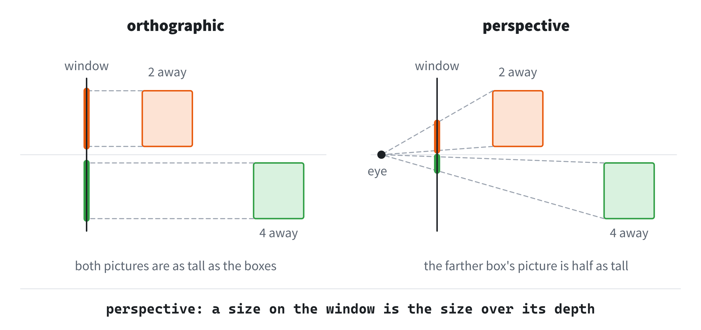
On the left, the lines run straight back, parallel to each other, so each box's picture is as tall as the box. That's an orthographic projection. On the right, the lines all meet at the eye. The farther box's lines meet at a narrower angle, so they cross the glass closer together, and its picture is half as tall. That's a perspective projection. Either way, three coordinates become two. The third is the depth, which is kept aside for deciding later what's in front.
View Space
Both projections assume the eye is at one place, looking one way. In this book, that's the origin, looking down the -z axis, with x to the right and y up. A point in front of the eye has a negative z, and its depth in front is -z. That arrangement is view space.
A camera anywhere else needs the world moved to suit it. As in Chapter 27, a view matrix does that, by undoing the camera's placement. Projector's camera never turns, and sits on the z axis at (0, 0, camDist). So its view matrix is a move of -camDist along z. Chapter 31 builds a camera that can sit anywhere and turn. A corner gets from its object's own space to the window in four steps:
- The model matrix places it in the world, as in Chapter 29.
- The view matrix moves it into view space.
- The projection matrix takes it to clip space.
- The divide by w, and a stretch, put it on the window.
This chapter is about steps 3 and 4.
Orthographic Projection
The Box
An orthographic projection takes a box of view space and squeezes it into a standard cube, from -1 to 1 on each axis. The box reaches halfHeight above and below the middle of the view. It reaches aspect times that to each side, where the aspect is the window's width over its height. It runs from the near plane, nearDist in front of the eye, to the far plane, farDist in front. Nothing outside the box is drawn. The standard cube is called normalized device coordinates, or NDC. Every projection ends there, so the last step, to the window, never needs to know which projection it was.
Each axis gets its own simple squeeze. The box's sides must go to -1 and 1, so x is divided by the half-width, and y by the half-height:
x' = x / (aspect * halfHeight)
y' = y / halfHeight
For z, write near and far for the planes' distances. The near plane is at z = -near, and it must go to -1. The far plane is at z = -far, and it must go to 1. A straight line through those two, z' = a z + b, meets both conditions:
-a * near + b = -1
-a * far + b = 1
Take the first from the second, and a (near - far) = 2, so a = -2 / (far - near). Put that back into the first, and b = -(far + near) / (far - near). Those are the four numbers of the matrix, and the first of the new builders in Mat4.h sets them. It goes after rotationZ:
// An orthographic projection, for a camera at the origin looking down
// -z. It squeezes a box into the cube from -1 to 1: halfHeight above and
// below the middle of the view, aspect times that to each side, and from
// nearDist to farDist in front. Its bottom row stays 0, 0, 0, 1.
static Mat4 orthographic(float halfHeight, float aspect, float nearDist,
                         float farDist)
{
    Mat4 r;
    r.m[0][0] = 1.0f / (aspect * halfHeight);
    r.m[1][1] = 1.0f / halfHeight;
    r.m[2][2] = -2.0f / (farDist - nearDist);
    r.m[2][3] = -(farDist + nearDist) / (farDist - nearDist);
    return r;
}
The first two numbers on the diagonal are the divides, as multiplications by 1 over the half-width and the half-height. The z row holds a and b. The bottom row is left as 0, 0, 0, 1, so w stays 1, and the divide by w that comes later changes nothing. That's why distance has no effect on size here: nothing in x' or y' depends on z.
A Left-Handed Cube
The z row turns depth around. In view space, z grows toward the eye. In NDC, the near plane is -1 and the far plane is 1, so z grows away from it. That's the natural order for comparing depths, since a bigger NDC z is farther away. But x still points right and y still points up, so with z pointing away, NDC is left-handed. Chapter 28 said a space inside the drawing process would be left-handed even in OpenGL, and this is that space. The flip is on purpose. It's the price of a depth that grows away from the eye, and everything after the projection is written for NDC as it is.
Perspective Projection
Similar Triangles
A perspective projection runs every line to the eye. Put the glass at a distance of 1 in front of the eye, and take a point at a height of y and a depth of -z. Its line to the eye crosses the glass at some height y'. The next image shows the view from the side.
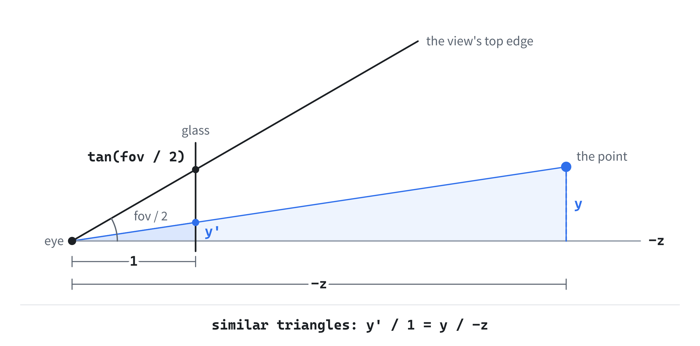
The line makes two right triangles that share the corner at the eye: a small one out to the glass, and a large one out to the point. They have the same angles, so they're similar, and their sides are in proportion:
y' / 1 = y / -zSo y' = y / -z, and in the same way, x' = x / -z. That's the whole of perspective: a point's place on the glass is its x and y divided by its depth. Double the depth, and the point lands half as far from the middle. So a thing's size on the window is in inverse proportion to its depth, which is why the farther box in Figure 30.1 had a picture half as tall.
The Divide by w
A matrix can't divide by z. Each number it makes is a sum of products, so it can multiply x by a constant, but never by 1 over z. It can do the next best thing, though. If its bottom row is 0, 0, -1, 0, the fourth coordinate it makes is w = -z, the depth. Then, after the matrix, the four coordinates are all divided by w. That's the perspective divide, and it's where distant things get smaller: not in the matrix, but in the division after it.
This w is the depth along the view's axis, -z, and not the straight-line distance from the eye. The point (1, 1, -5) is 5.20 from the eye in a straight line, but its w is 5. Every point of a flat wall facing the eye has the same w. So the whole wall is divided by one number, and its picture is the wall made smaller, with its shape kept.
So far, apply has worked out three rows and assumed the fourth. A projection's fourth row matters, so Mat4.h gets a type that keeps all four coordinates. It goes before the Mat4 struct, with a blank line on each side:
// Vec4: a point in four coordinates, with its w kept (Chapter 30), as a
// projection leaves it. A new one is (0, 0, 0, 1).
struct Vec4
{
    float x = 0.0f;
    float y = 0.0f;
    float z = 0.0f;
    float w = 1.0f;
};
A new Vec4 is the point (0, 0, 0, 1). Then, after applyDir, comes a version of apply that works out the fourth row too:
// A point, transformed, with its fourth coordinate kept: all four rows
// dotted with (x, y, z, 1). For a projection, the bottom row isn't
// 0, 0, 0, 1, so w isn't 1.
Vec4 apply4(Vec3 p) const
{
    return { m[0][0] * p.x + m[0][1] * p.y + m[0][2] * p.z + m[0][3],
             m[1][0] * p.x + m[1][1] * p.y + m[1][2] * p.z + m[1][3],
             m[2][0] * p.x + m[2][1] * p.y + m[2][2] * p.z + m[2][3],
             m[3][0] * p.x + m[3][1] * p.y + m[3][2] * p.z + m[3][3] };
}
For a transform whose bottom row is 0, 0, 0, 1, its w comes out as 1. For a projection, w is whatever the bottom row makes it.
The Field of View
A perspective projection still has to squeeze its view into the NDC cube. Its view isn't a box, but a pyramid with its tip at the eye and its top cut off by the near plane: a frustum. Its shape comes from the field of view, the angle from the bottom of the view to its top. Look again at Figure 30.2. The view's top edge leaves the eye at half the field of view, so at a distance of 1, the top of the view is tan(fov / 2) above the middle. That height on the glass has to become 1 in NDC. So y' is divided by it, which is a multiplication by f:
f = 1 / tan(fov / 2)And x is multiplied by f / aspect, since the view is wider than it's tall by the window's aspect. At 60 degrees, tan 30° is 0.577, so f is 1.732. With Projector's window, 1000 by 700, the aspect is 1.429, and f / aspect is 1.212. A wider field of view makes f smaller, so everything is drawn smaller, and more of the world fits.
The Depth Row
The z row has the orthographic one's job: the near plane must go to -1, and the far plane to 1. But now the result is divided by w. Call the z row's two numbers A and B. The matrix makes A z + B, and NDC's z is that over w, which is -z. At the near plane, z is -near and w is near. At the far plane, z is -far and w is far. So the two conditions are:
(-A * near + B) / near = -1
(-A * far + B) / far = 1
Multiply each through by its w:
-A * near + B = -near
-A * far + B = far
Take the first from the second, and -A (far - near) = far + near, so A = (far + near) / (near - far). Put that back into the first, and B = 2 * far * near / (near - far). The whole matrix is then:
| f / aspect   0    0    0 |
| 0            f    0    0 |
| 0            0    A    B |
| 0            0   -1    0 |
The second new builder in Mat4.h, after orthographic, sets those numbers:
// A perspective projection, for a camera at the origin looking down -z,
// with a field of view, fovY, from the bottom of the view to its top, in
// radians. The view's half-height at a distance of 1 is tan(fovY / 2),
// and f is 1 over that. The bottom row puts the depth in front, -z, into
// w, so that the divide by w makes distant things smaller.
static Mat4 perspective(float fovY, float aspect, float nearDist,
                        float farDist)
{
    float f = 1.0f / std::tan(fovY * 0.5f);
    Mat4 r;
    r.m[0][0] = f / aspect;
    r.m[1][1] = f;
    r.m[2][2] = (farDist + nearDist) / (nearDist - farDist);
    r.m[2][3] = 2.0f * farDist * nearDist / (nearDist - farDist);
    r.m[3][2] = -1.0f;
    r.m[3][3] = 0.0f;
    return r;
}
Every number on the diagonal is set, the last one to 0, so nothing of the identity is left over. The -1 in the bottom row is the one that makes it a perspective, by putting -z into w. With Projector's planes, 0.5 and 40, A is -1.025 and B is -1.013. The next image shows what the matrix and the divide do together, seen from the side.
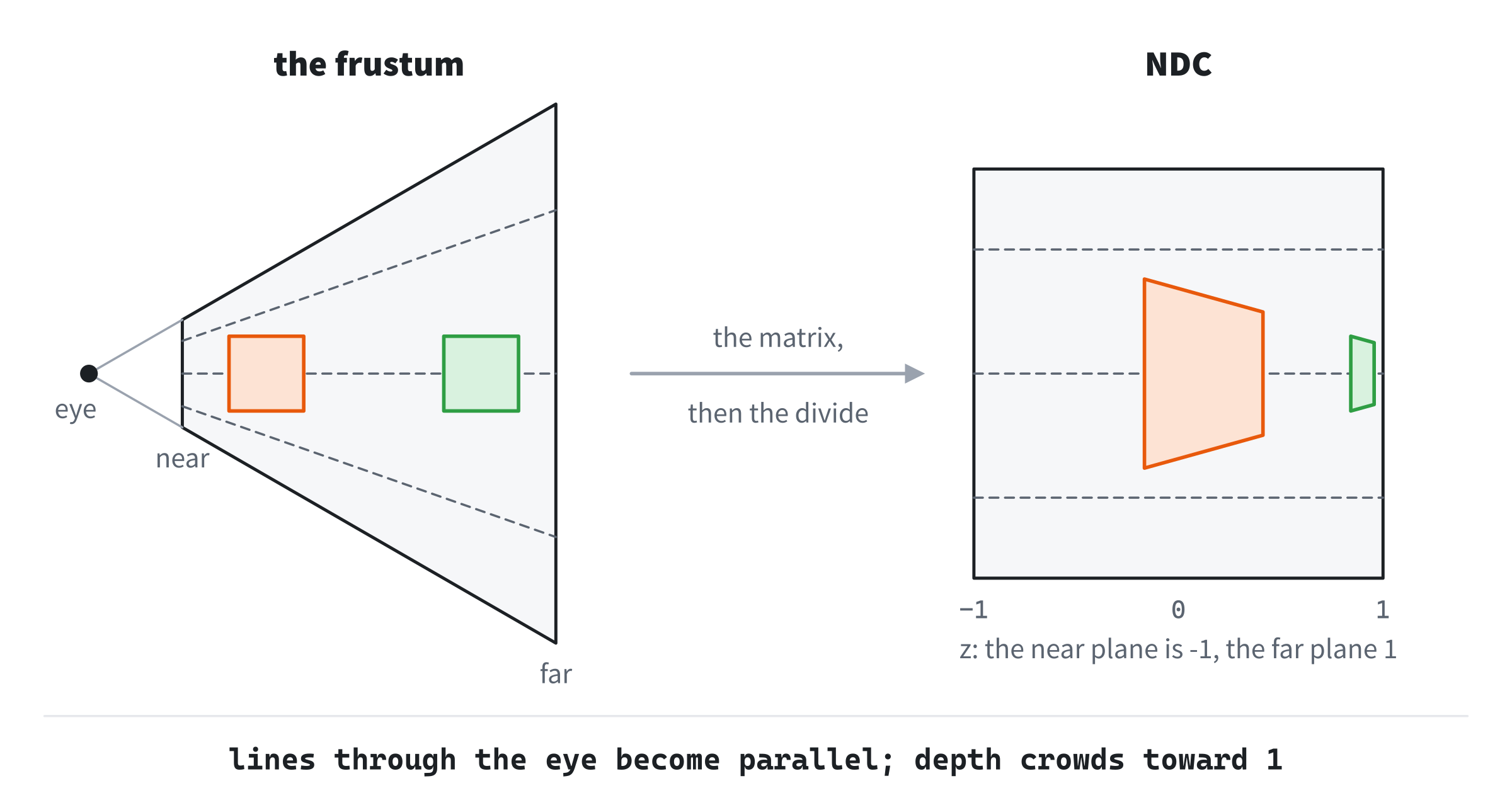
The frustum's sloping sides become the cube's flat ones. A point on the top edge has a height of tan(fov / 2) times its depth, and the divide makes that 1 at every depth. So lines through the eye become parallel. The near plane is small, and it's stretched to fill the cube's face. The far plane is large, and it's shrunk to the same size. So a box near the eye fills much of the cube, and the same box far away fills little of it, squeezed up against the far side.
A Zoom, or a Move
It's often said that a wide field of view exaggerates depth, and a narrow one flattens it. But f multiplies the x and y of every point by the same number, whatever its depth. So changing the field of view, with the camera where it is, is a pure zoom. Everything on the window grows or shrinks together, about the middle, and near and far things keep the ratio of their sizes.
What changes that ratio is the camera's distance. Projector's first cube is 6 in front of the camera, and its last is 18, so the last looks a third the size of the first. Move the camera back 6, so that they're 12 and 24 away, and the last looks half the size of the first. The next image shows both changes.
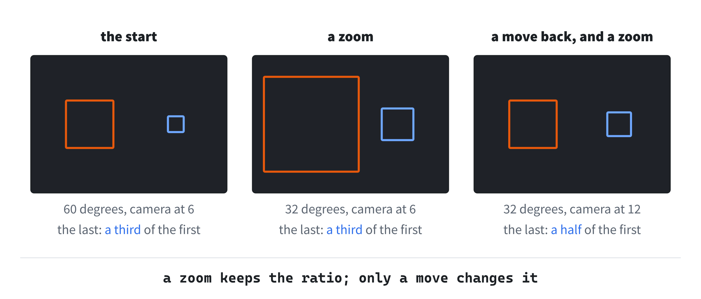
In the middle, the field of view is narrowed to 32 degrees, which halves tan(fov / 2), and both cubes double in size. On the right, the camera has also moved back to 12, which brings the first cube back to its starting size. Now the last cube is half the size of the first. That's a dolly zoom. Films use it to make the background seem to rush toward someone, or away, while they stay the same size. So the flat look of a long lens comes from standing far away, and the stretched look of a wide one from standing close.
Depth After the Divide
Uneven Depth
The divide does something to depth, too. Divide the z row's A z + B by w, and write d for the depth, -z:
NDC z = (far + near) / (far - near) - 2 * far * near / ((far - near) * d)The first part is a constant, and the second shrinks as 1 over d. So NDC's z isn't spread evenly over the depths. It climbs steeply just past the near plane, and then creeps toward 1. It's 0, halfway through its range, at the depth:
d = 2 * far * near / (far + near)That's just under twice the near plane's distance. The next image shows the curve, for Projector's planes.

With a near plane of 0.5 and a far plane of 40, half of NDC's range covers the depths from 0.5 to 0.99. Projector's cubes sit at depths from 6 to 18, and they get NDC depths from 0.857 to 0.969, under 6 percent of the range. Everything from the first cube out to the far plane, 34 units of the scene, shares 7 percent of it. An orthographic projection has no divide, so its depths are spread evenly, and the same cubes get -0.72 to -0.11.
Choosing the Planes
That unevenness matters because depths get compared. Chapter 33 keeps a depth for every pixel of the window, and draws a new surface's pixel only where it's nearer than what's already there. Its depths are floats, and a float near 1 can only hold so many different values. When two surfaces' depths round to the same float, the comparison can't tell which is in front. They flicker through each other as the camera moves, which is called z-fighting.
The near plane decides most of it. With a near plane of 0.1 and a far plane of 100, half the range goes on the depths between 0.1 and 0.2. With a near plane of 0.001 and a far plane of 1000, two walls at depths of 500 and 501 get the same float. So the rule is to push the near plane out as far as the scene allows. The far plane matters much less, since the curve has nearly flattened out by then. A near plane of 0 is the worst of all. Then A is -1 and B is 0, so every depth comes out as 1, and depth tells nothing at all.
Projector's Q and E keys move its near plane, so that you can watch the cubes' NDC depths spread out as it moves away from the camera.
One Point, End to End
Clip Space
Follow one point through the perspective projection, with Projector's settings: a field of view of 60 degrees, an aspect of 1000 over 700, and planes at 0.5 and 40. The point is (1, 1, -5) in view space. The matrix takes it to clip space, four coordinates before the divide:
x = 1.212 * 1 = 1.212
y = 1.732 * 1 = 1.732
z = -1.025 * -5 - 1.013 = 4.114
w = -(-5) = 5
Clip space is where a point is tested against the frustum, before anything is divided by w. A point is inside when its x, y and z are each between -w and w. That's NDC's -1 to 1, multiplied through by w, which is positive in front of the eye. For z, the test is the same as the depth being between the near and far planes. Here, 4.114 is between -5 and 5, and the depth of 5 is between 0.5 and 40. Testing before the divide is safer, too. A point beside the eye, at a depth of 0, has a w of 0, and it fails the test before anything divides by it.
Projector tests z only. A corner outside the near or far plane is dropped, with every edge that meets it. A real renderer clips instead: it cuts each edge where it crosses a plane, and keeps the part inside. Chapter 32 does that for the near plane. Projector doesn't test x and y, since SDL draws a line that runs off the window without complaint.
The Divide and the Viewport
The divide gives the point in NDC:
(1.212 / 5, 1.732 / 5, 4.114 / 5) = (0.242, 0.346, 0.823)The last step stretches NDC's square across the window, as the viewport transform. NDC's x runs from -1 at the left edge to 1 at the right. Its y runs from -1 at the bottom to 1 at the top, but the window's y runs down, so y is flipped:
windowX = (x * 0.5 + 0.5) * WINDOW_WIDTH
windowY = (0.5 - y * 0.5) * WINDOW_HEIGHT
So the point lands 0.621 of the way across the window and 0.327 of the way down, at the pixel (621, 229). NDC's z, 0.823, takes no part in placing it, and is kept for comparing depths.
Building Projector
Projector draws five cubes of the same size, in a row going away from the camera. Space swaps between the perspective and orthographic projections. Up and Down change the field of view, and W and S move the camera. Q and E move the near plane, and Z and X the far plane. Along the bottom, two rulers show each cube's depth in front of the camera, and the NDC depth the projection gives it. At the top, the readout shows the projection matrix, and how tall a unit is at the first cube and at the last.
Get the code. The complete project is in the
Projectorfolder of the book's repository.
Projector starts from the skeleton, with its timing. It reads the mouse's movement but not its position, as Transforming a Cube did. It reuses fmt2 from Chapter 4, setColor from Chapter 8 and padded from Chapter 26. Its Vec2.h and Vec3.h are Transforming a Cube's, and its Mat4.h is the one this chapter grew. Here are its includes and its colors:
#include <cmath>
#include <string>
#include "Vec2.h"
#include "Vec3.h"
#include "Mat4.h"

constexpr int WINDOW_WIDTH  = 1000;
constexpr int WINDOW_HEIGHT = 700;

constexpr SDL_Color TEXT = { 235, 238, 242, 255 };
constexpr SDL_Color GREY = { 90, 100, 112, 255 };
constexpr SDL_Color AMBER = { 240, 200, 60, 255 };

// The five cubes' colors, from the nearest to the farthest.
constexpr SDL_Color CUBE_COLOR[5] = { { 235, 85, 85, 255 },
                                      { 245, 150, 50, 255 },
                                      { 90, 205, 110, 255 },
                                      { 90, 160, 245, 255 },
                                      { 190, 125, 245, 255 } };
The projection matrix's bottom row is drawn in amber. Each cube has its own color, which its marks on the rulers share. Then come the constants:
// The window's width over its height. The projection needs it, so that a
// cube is as wide on the window as it's tall.
constexpr float ASPECT = (float)WINDOW_WIDTH / (float)WINDOW_HEIGHT;

// How fast the controls change things, a second, and their limits: the
// field of view, in degrees, the camera's distance, and the near and far
// planes' distances in front of the camera. Then the spin, and how far a
// drag turns the cubes, a pixel.
constexpr float FOV_SPEED = 25.0f;
constexpr float MIN_FOV = 20.0f;
constexpr float MAX_FOV = 110.0f;
constexpr float DOLLY_SPEED = 3.0f;
constexpr float MIN_DIST = 2.0f;
constexpr float MAX_DIST = 22.0f;
constexpr float NEAR_SPEED = 2.0f;
constexpr float FAR_SPEED = 8.0f;
constexpr float MIN_NEAR = 0.1f;
constexpr float MAX_FAR = 50.0f;
constexpr float SPIN_X = 0.2f;
constexpr float SPIN_Y = 0.5f;
constexpr float DRAG_TURN = 0.01f;
The aspect is worked out once, as a float division, 1.429. The field of view runs from 20 to 110 degrees, and the camera from 2 to 22 units from the first cube. The near plane can come as close as 0.1, and the far plane go out to 50. Last come the rulers' places:
// The rulers along the bottom: where their ends are on the window, how far
// down each one is, and the distance in front of the camera that the first
// one reaches.
constexpr float RULER_LEFT = 130.0f;
constexpr float RULER_RIGHT = 950.0f;
constexpr float DIST_Y = 570.0f;
constexpr float DEPTH_Y = 616.0f;
constexpr float RULER_DIST = 50.0f;
The first ruler reaches 50 units in front of the camera, as far as the far plane can go.
Two Helpers
Two new functions go before main. The first finds a place along a ruler:
// A place on a ruler, from a fraction of the way along it: 0 at its left
// end and 1 at its right.
float rulerX(float t)
{
    return RULER_LEFT + SDL_clamp(t, 0.0f, 1.0f) * (RULER_RIGHT - RULER_LEFT);
}
The fraction is clamped, so that a mark beyond either end stays at that end. The second takes a point all the way to the window:
// A point on the window, from the matrix that takes it to clip space: the
// depth test, the divide by w, and the stretch across the window. For a
// point outside the near and far planes, it returns false.
bool toWindow(const Mat4& toClip, Vec3 p, Vec2& out)
{
    Vec4 c = toClip.apply4(p);
    if (c.z < -c.w || c.z > c.w) return false;
    Vec2 ndc = { c.x / c.w, c.y / c.w };
    out = { (ndc.x * 0.5f + 0.5f) * WINDOW_WIDTH,
            (0.5f - ndc.y * 0.5f) * WINDOW_HEIGHT };
    return true;
}
Its first argument is the matrix that takes the point to clip space. That can be the projection alone, or the model, the view and the projection, multiplied together. The function tests z against w, divides by w, and stretches NDC across the window, as the last section did by hand. For a point that fails the test, it returns false and leaves out alone.
The State
The state goes after the font is loaded. First comes one cube:
// A cube in its own space, 1.6 units on a side: eight corners at every
// mix of -0.8 and 0.8, and twelve edges, as Transforming a Cube's were.
const Vec3 CORNER[8] = { { -0.8f, -0.8f, -0.8f }, { 0.8f, -0.8f, -0.8f },
                         { 0.8f, 0.8f, -0.8f }, { -0.8f, 0.8f, -0.8f },
                         { -0.8f, -0.8f, 0.8f }, { 0.8f, -0.8f, 0.8f },
                         { 0.8f, 0.8f, 0.8f }, { -0.8f, 0.8f, 0.8f } };
const int EDGE[12][2] = { { 0, 1 }, { 1, 2 }, { 2, 3 }, { 3, 0 },
                          { 4, 5 }, { 5, 6 }, { 6, 7 }, { 7, 4 },
                          { 0, 4 }, { 1, 5 }, { 2, 6 }, { 3, 7 } };
It's Transforming a Cube's cube, 1.6 units on a side instead of 2, with its edges in the same order. Then come the five cubes' places:
// The five cubes' centers, in a row going away from the camera, each 3
// units behind the one before, and 1.8 to its right, so that none hides
// another.
const Vec3 CENTER[5] = { { -3.6f, 0.0f, 0.0f }, { -1.8f, 0.0f, -3.0f },
                         { 0.0f, 0.0f, -6.0f }, { 1.8f, 0.0f, -9.0f },
                         { 3.6f, 0.0f, -12.0f } };
The first cube has a z of 0, 3.6 to the left of the origin, and each of the others is 3 units farther along -z. Each is also 1.8 to the right of the one before, so that none hides another. Then come the controls:
// The projection and its controls: which kind, the field of view in
// degrees, the camera's z, and the near and far planes' distances in
// front of the camera. Then the cubes' turn, whether they spin, and
// whether they're being dragged.
bool ortho = false;
float fovDeg = 60.0f;
float camDist = 6.0f;
float nearDist = 0.5f;
float farDist = 40.0f;
float rx = 0.4f;
float ry = 0.5f;
bool spin = true;
bool dragging = false;
The projection starts as a perspective, with a field of view of 60 degrees and the planes at 0.5 and 40. The camera starts 6 units in front of the first cube. Those are the settings of the last section's point. The cubes start turned 0.4 radians about x and 0.5 about y, and spinning.
The Events
Space swaps the projection, R puts everything back, and a drag turns the cubes:
// Events: quitting, and the keys and clicks that happen once. A drag
// turns the cubes, as in Transforming a Cube, and stops their spin.
SDL_Event event;
while (SDL_PollEvent(&event))
{
    if (event.type == SDL_EVENT_QUIT) running = false;
    else if (event.type == SDL_EVENT_KEY_DOWN)
    {
        if (event.key.key == SDLK_ESCAPE) running = false;
        else if (event.key.key == SDLK_SPACE) ortho = !ortho;
        else if (event.key.key == SDLK_R)
        {
            ortho = false;
            fovDeg = 60.0f;
            camDist = 6.0f;
            nearDist = 0.5f;
            farDist = 40.0f;
            rx = 0.4f;
            ry = 0.5f;
            spin = true;
        }
    }
    else if (event.type == SDL_EVENT_MOUSE_BUTTON_DOWN &&
             event.button.button == SDL_BUTTON_LEFT)
    {
        dragging = true;
        spin = false;
    }
    else if (event.type == SDL_EVENT_MOUSE_BUTTON_UP) dragging = false;
    else if (event.type == SDL_EVENT_MOUSE_MOTION && dragging)
    {
        ry += event.motion.xrel * DRAG_TURN;
        rx += event.motion.yrel * DRAG_TURN;
    }
}
In the preceding code, a drag works as Transforming a Cube's did, turning the cubes a hundredth of a radian a pixel. It stops the spin, and so does a click without a drag. R starts the spin again.
Each Frame's Work
Each frame, the keys that are held change the controls:
// Keys held down change the field of view, move the camera, and move
// the near and far planes, each within its limits. The near plane
// stops 1 short of the far one, and the far plane 1 beyond the near
// one. The cubes spin while they're left alone.
const bool* keys = SDL_GetKeyboardState(nullptr);
if (keys[SDL_SCANCODE_UP]) fovDeg += FOV_SPEED * dt;
if (keys[SDL_SCANCODE_DOWN]) fovDeg -= FOV_SPEED * dt;
fovDeg = SDL_clamp(fovDeg, MIN_FOV, MAX_FOV);
if (keys[SDL_SCANCODE_W]) camDist -= DOLLY_SPEED * dt;
if (keys[SDL_SCANCODE_S]) camDist += DOLLY_SPEED * dt;
camDist = SDL_clamp(camDist, MIN_DIST, MAX_DIST);
if (keys[SDL_SCANCODE_Q]) nearDist -= NEAR_SPEED * dt;
if (keys[SDL_SCANCODE_E]) nearDist += NEAR_SPEED * dt;
nearDist = SDL_clamp(nearDist, MIN_NEAR, farDist - 1.0f);
if (keys[SDL_SCANCODE_Z]) farDist -= FAR_SPEED * dt;
if (keys[SDL_SCANCODE_X]) farDist += FAR_SPEED * dt;
farDist = SDL_clamp(farDist, nearDist + 1.0f, MAX_FAR);
if (spin)
{
    ry += SPIN_Y * dt;
    rx += SPIN_X * dt;
}
In the preceding code, each control is clamped to its limits after its keys change it. The near plane is clamped before the far plane's keys are read, so that each plane stops 1 unit short of the other. Then the projection and the view are built:
// The projection, from the controls. The orthographic box is as tall
// as the perspective view is at the first cube, so that the first
// cube is the same size in both. The camera sits at (0, 0, camDist),
// looking down -z, and the view matrix undoes that, with a move.
float fov = fovDeg * PI / 180.0f;
float halfHeight = std::tan(fov * 0.5f) * camDist;
Mat4 proj = Mat4::perspective(fov, ASPECT, nearDist, farDist);
if (ortho)
    proj = Mat4::orthographic(halfHeight, ASPECT, nearDist, farDist);
Mat4 view = Mat4::translation(0.0f, 0.0f, -camDist);
Mat4 R = Mat4::rotationY(ry) * Mat4::rotationX(rx);
The field of view is turned into radians. Then halfHeight is the perspective view's half-height at the first cube's depth, which is tan(fov / 2) times camDist. The orthographic box is given that half-height, so that a unit at the first cube is the same size in both projections. Then Space shows only what depth changes. The view matrix is the move that takes the camera back to the origin. The cubes all share one turn, R.
Drawing
After the skeleton clears the screen, the cubes are drawn:
// The cubes. One matrix takes each corner from its cube's own space
// to clip space: the projection, times the view, times the model.
// Then toWindow puts the corner on the window, if it passes the depth
// test, and an edge is drawn if both its corners did.
for (int i = 0; i < 5; ++i)
{
    Vec3 c = CENTER[i];
    Mat4 model = Mat4::translation(c.x, c.y, c.z) * R;
    Mat4 toClip = proj * view * model;
    Vec2 at[8];
    bool inside[8];
    for (int k = 0; k < 8; ++k)
        inside[k] = toWindow(toClip, CORNER[k], at[k]);
    setColor(renderer, CUBE_COLOR[i]);
    for (int e = 0; e < 12; ++e)
    {
        int a = EDGE[e][0];
        int b = EDGE[e][1];
        if (!inside[a] || !inside[b]) continue;
        SDL_RenderLine(renderer, at[a].x, at[a].y, at[b].x, at[b].y);
    }
}
In the preceding code, proj * view * model is one matrix that takes a corner from its cube's own space to clip space. Read from the right, it places the corner in the world, moves it into view space and projects it. It's built once for each cube, and then each corner costs one apply4. Every corner is put on the window once, with its result kept. Then each edge is drawn if both its ends passed the depth test. So when a corner crosses the near or far plane, the three edges that meet there vanish with it. Then come the strips that the readout and the rulers sit on:
// Strips of the background's color for the readout and the rulers,
// so that the cubes don't show through the text.
SDL_SetRenderDrawColor(renderer, 24, 26, 30, 255);
SDL_FRect top = { 0.0f, 0.0f, (float)WINDOW_WIDTH, 104.0f };
SDL_FRect bottom = { 0.0f, 548.0f, (float)WINDOW_WIDTH, 152.0f };
SDL_RenderFillRect(renderer, &top);
SDL_RenderFillRect(renderer, &bottom);
These are Camera's strips, from Chapter 27, sized for this demo's readout and rulers. Then come the rulers:
// The rulers. The first shows distance in front of the camera, from 0
// to 50, with the space between the near and far planes shaded. The
// second shows the depth after the divide, from -1 to 1.
float nearX = rulerX(nearDist / RULER_DIST);
float farX = rulerX(farDist / RULER_DIST);
SDL_SetRenderDrawColor(renderer, 38, 62, 50, 255);
SDL_FRect band = { nearX, DIST_Y - 8.0f, farX - nearX, 16.0f };
SDL_RenderFillRect(renderer, &band);
setColor(renderer, GREY);
SDL_RenderLine(renderer, RULER_LEFT, DIST_Y, RULER_RIGHT, DIST_Y);
SDL_RenderLine(renderer, RULER_LEFT, DEPTH_Y, RULER_RIGHT, DEPTH_Y);
setColor(renderer, TEXT);
SDL_RenderLine(renderer, nearX, DIST_Y - 12.0f, nearX, DIST_Y + 12.0f);
SDL_RenderLine(renderer, farX, DIST_Y - 12.0f, farX, DIST_Y + 12.0f);
drawText(renderer, font, "distance", 12, DIST_Y - 10, TEXT);
drawText(renderer, font, "near", nearX - 42, DIST_Y + 8, TEXT);
drawText(renderer, font, "far", farX + 6, DIST_Y + 8, TEXT);
drawText(renderer, font, "NDC z", 12, DEPTH_Y - 10, TEXT);
drawText(renderer, font, "-1", RULER_LEFT - 10, DEPTH_Y + 6, GREY);
drawText(renderer, font, "0", 536, DEPTH_Y + 6, GREY);
drawText(renderer, font, "1", RULER_RIGHT - 5, DEPTH_Y + 6, GREY);
In the preceding code, the shaded band on the first ruler runs from the near plane to the far one, so it shows which depths pass the test. The near plane's label goes to the left of its line, and the far plane's to the right, so that the two never overlap. Then come each cube's marks:
// Each cube's marks, in its color: at its center's distance in front
// of the camera, and at the depth the projection gives it. A cube
// whose center fails the depth test has a grey mark on the first
// ruler, and none on the second.
for (int i = 0; i < 5; ++i)
{
    Vec3 v = view.apply(CENTER[i]);
    Vec4 c = proj.apply4(v);
    bool inside = c.z >= -c.w && c.z <= c.w;
    setColor(renderer, inside ? CUBE_COLOR[i] : GREY);
    SDL_FRect mark = { rulerX(-v.z / RULER_DIST) - 2.0f, DIST_Y - 8.0f,
                       4.0f, 16.0f };
    SDL_RenderFillRect(renderer, &mark);
    if (!inside) continue;
    mark.x = rulerX((c.z / c.w + 1.0f) * 0.5f) - 2.0f;
    mark.y = DEPTH_Y - 8.0f;
    SDL_RenderFillRect(renderer, &mark);
}
Each cube's center is taken into view space, where its depth, -z, places its mark on the first ruler. Then the projection takes it to clip space. If it passes the depth test, its NDC z places its mark on the second ruler, from -1 to 1. A cube whose center fails the test gets a grey mark on the first ruler, and none on the second. Last come the readout and the controls:
// The readout: the projection and the controls, then how tall a unit
// is on the window at the first cube and at the last. A point 1 above
// the middle of the view, at each one's z, is taken to clip space and
// divided by w, and half the window's height is 1 in NDC.
std::string kind = "perspective, field of view " +
                   std::to_string((int)std::lround(fovDeg)) +
                   " degrees";
if (ortho)
    kind = "orthographic, a box " + fmt2(2.0f * halfHeight) + " tall";
drawText(renderer, font, kind, 12, 10, TEXT);
drawText(renderer, font,
         "camera at z " + fmt2(camDist) + ", near " + fmt2(nearDist) +
         ", far " + fmt2(farDist), 12, 32, TEXT);
Mat4 viewProj = proj * view;
Vec4 first = viewProj.apply4({ 0.0f, 1.0f, CENTER[0].z });
Vec4 last = viewProj.apply4({ 0.0f, 1.0f, CENTER[4].z });
int firstPx = (int)std::lround(first.y / first.w * WINDOW_HEIGHT / 2);
int lastPx = (int)std::lround(last.y / last.w * WINDOW_HEIGHT / 2);
drawText(renderer, font,
         "a unit is " + std::to_string(firstPx) +
         " px tall at the first cube, " + std::to_string(lastPx) +
         " at the last", 12, 54, TEXT);
The first line says which projection is in use, with the field of view for the perspective, and the box's height for the orthographic. The third line measures the projection itself. A point 1 above the middle of the view, at the first cube's z, is taken to clip space and divided by w. Its NDC y is how far above the window's middle it lands, as a share of half the window's height. So multiplying by 350, half of 700, gives a unit's height in pixels. The same is done at the last cube's z. Then come the matrix and the controls:
// The projection matrix, with its bottom row, which makes w, in amber.
// Then the controls.
for (int i = 0; i < 4; ++i)
    for (int j = 0; j < 4; ++j)
        drawText(renderer, font, padded(proj.m[i][j], 3),
                 640 + j * 86.0f, 10 + i * 22.0f,
                 i == 3 ? AMBER : TEXT);
drawText(renderer, font,
         "[Space] perspective or orthographic   [Up] [Down] field of "
         "view   [Drag] turn", 12, WINDOW_HEIGHT - 46, GREY);
drawText(renderer, font,
         "[W] [S] move the camera   [Q] [E] near plane   [Z] [X] far "
         "plane   [R] reset   [Esc] quit", 12, WINDOW_HEIGHT - 26,
         GREY);
The projection matrix is drawn with padded from Chapter 26, to three decimals, with its bottom row in amber. There's nothing to add to the skeleton's cleanup.
Trying It Out
Run the demo. Five cubes go off into the distance, each smaller than the one before, turning slowly. Then try it, step by step:
- Swap the projections. Press Space. The cubes snap to one size in an even row, and the readout says a unit is 101 pixels tall at both. The matrix's bottom row turns to
0, 0, 0, 1, and the marks on the second ruler spread out evenly. Press Space again to bring the depth back. - Zoom. Hold Up to widen the field of view, or Down to narrow it. All the cubes grow or shrink together, and the readout's two numbers keep their ratio: the last cube's unit stays a third of the first's.
- Move the camera. Hold W to move nearer, or S to move away. Now the ratio changes. With the camera 2 units from the first cube, the last is a seventh of its size, and at 22, nearly two thirds. The row looks deep from close up, and flat from far away.
- Move the near plane. Hold E. The near plane's line moves along the first ruler, and when it reaches the red cube, the red cube's edges start to vanish. Each corner that crosses the plane takes the edges that meet there with it. They go over about 1.4 units either side of the cube's mark, since a corner can be as far as 1.39 from the center. Once the center has crossed, the mark turns grey.
- Watch the depths spread. With the near plane at about 5, the cubes' NDC depths spread from about -0.6 to 0.65. Hold Q to bring the near plane back to 0.1, and watch them crowd up against 1.
- Move the far plane. Hold Z, and the far cubes vanish as the far plane passes them. X moves it back out.
- Move the camera in orthographic. Press Space, then hold W or S. The cubes still grow and shrink, all together. Depth has no effect on an orthographic projection's sizes, but this one's box is sized from the camera's distance, to match the perspective view at the first cube.
The next image shows the demo as it starts, with the spin stopped.
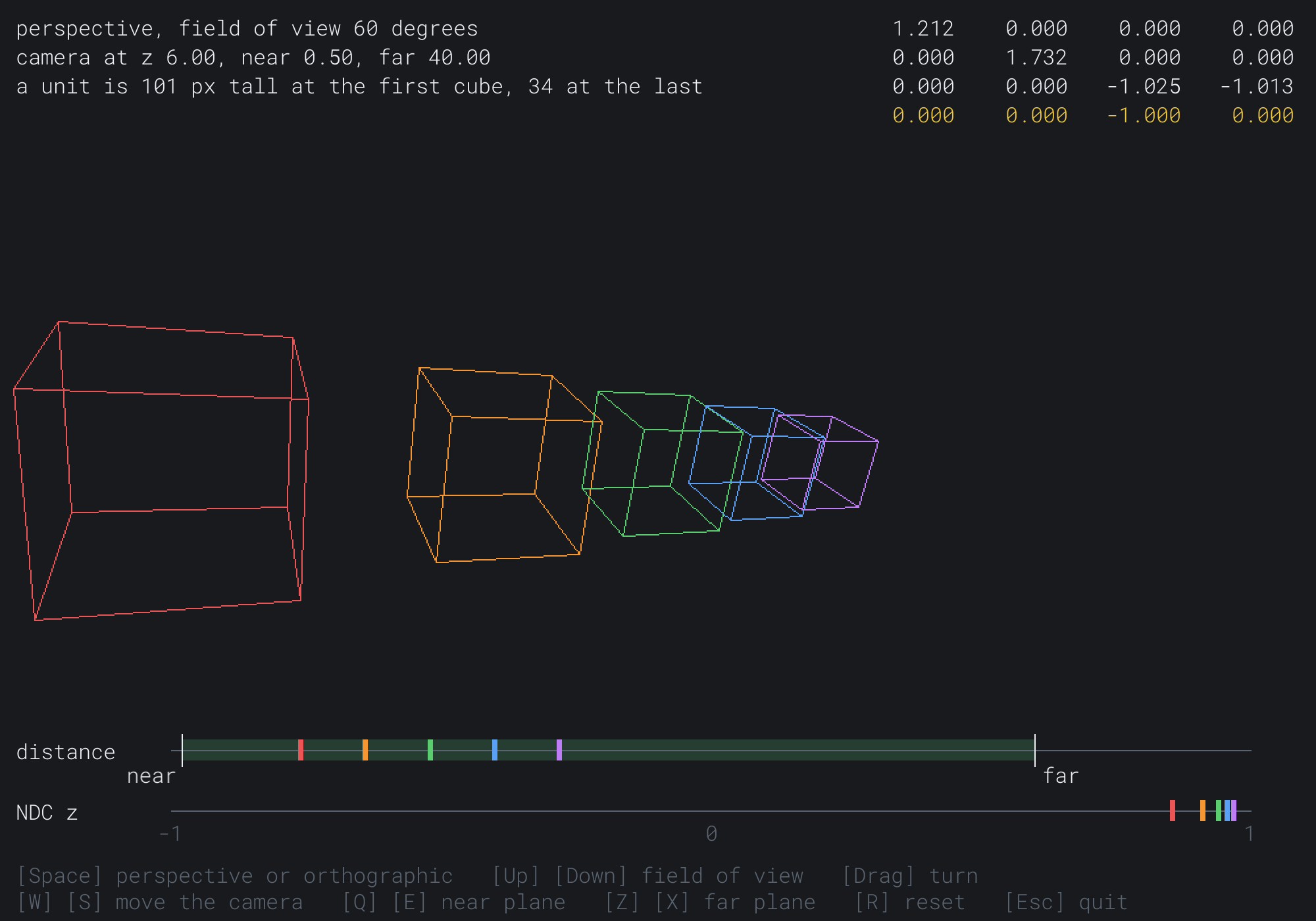
The matrix holds the last section's numbers: 1.212 and 1.732 on the diagonal, -1.025 and -1.013 in the z row, and the -1 in the bottom row. A unit is 101 pixels tall at the first cube and 34 at the last, a third, since the last is three times as deep. The second ruler shows the five cubes' NDC depths crowded between 0.857 and 0.969. The next image shows the same view after Space.
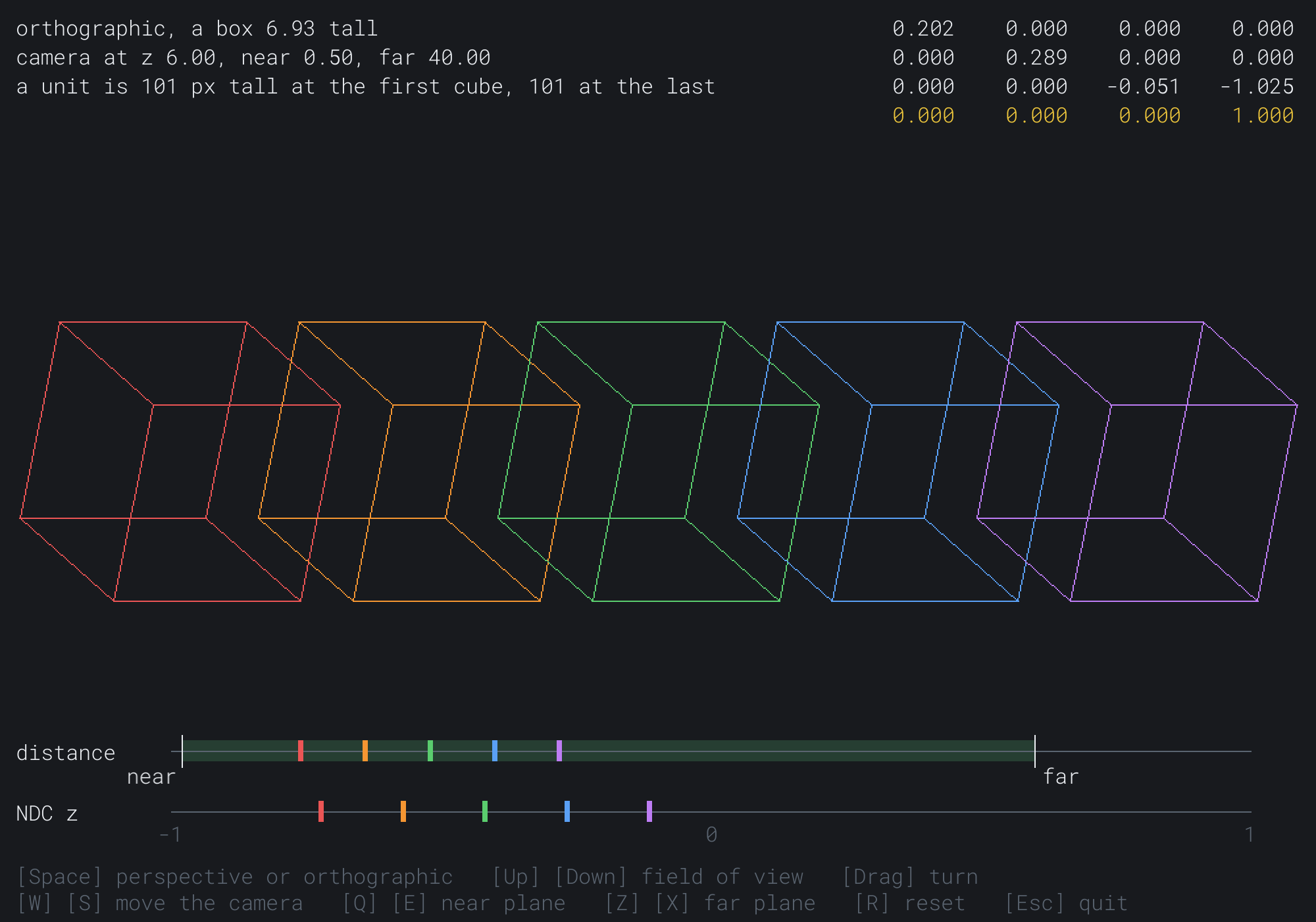
The cubes are all one size, and the bottom row is 0, 0, 0, 1. The diagonal now holds 1 over the box's half-width and half-height, 0.202 and 0.289. The NDC depths are evenly spaced, from -0.72 to -0.11. The next image shows the perspective again, with the near plane moved out to 5.6, through the red cube.
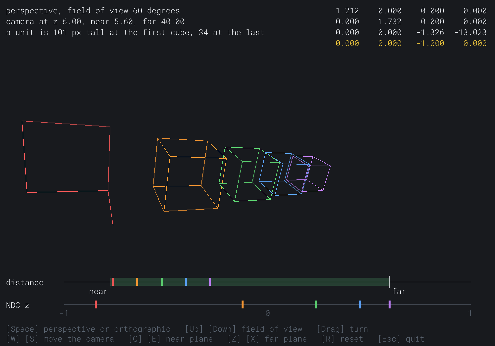
Three of the red cube's corners are nearer than 5.6, and the seven edges that meet them are gone. Its center, at 6, still passes the test, so its mark is still red. The NDC depths now spread from -0.85 to 0.60, across most of the range, and the matrix's z row has grown to -1.326 and -13.023.
FAQ
Q) My game's settings say a field of view of 90 degrees. Why does this code use 60?
A) Games often give the horizontal field of view, and this code's is vertical. At Projector's aspect, a vertical 60 degrees is 79 degrees across, and a horizontal 90 degrees is a vertical 70. The horizontal angle is 2 * atan(tan(fovY / 2) * aspect).
Q) Why do things near the edges of a wide view look stretched?
A) The projection is right, but the eye is in the wrong place. A perspective picture is exact for an eye at one spot in front of the screen, where the screen covers the same angle as the field of view. For a wide field of view, that spot is very close to the screen. Seen from farther back, things near the edges look stretched away from the middle, since they were drawn to be seen at a slant.
Q) My reference puts the -1 somewhere else, or makes depth run from 0 to 1. Which is right?
A) Both can be. Some references write a point as a row, on the left of the matrix, which transposes every matrix: the -1 moves to row 2, column 3. Direct3D, Vulkan and Metal put NDC's z between 0 and 1, which changes A and B. Vulkan's NDC y also points down. The derivation is the same each time, with different conditions, and Exercise 6 does the 0 to 1 version.
Exercises
The first three exercises need only a pencil. The others change Projector.
- Similar triangles (paper). A point is at
(2, 1, -4)in view space. Where does its line to the eye cross the glass, at a distance of 1? - The depth row (paper). For a near plane of 1 and a far plane of 10, find A and B. Then find the NDC z of a point at a depth of 2.
- Halfway (paper). For a near plane of 1 and a far plane of 1000, at what depth is NDC's z 0? What share of the range is left for everything farther away?
- A dolly zoom (code). Add a key that keeps the first cube's size while W and S move the camera. When it's pressed, keep
halfHeight, and each frame after, set the field of view from it andcamDist. - Clip x and y too (code). Make
toWindowfail a point whose x or y is outside -w to w as well, and count the edges drawn. Why does a cube near the window's edge now lose edges that were partly on the window? - Depth from 0 to 1 (challenge). Change
perspectiveso that the near plane goes to 0 and the far plane to 1, as Direct3D's does. Work out A and B from the two new conditions, and change the depth test intoWindowto match.
For the code exercises, work on a copy of the demo's folder, so that the original stays as the chapter describes it.
AI Exercise (Optional)
A projection is all a starfield needs. With an AI's help, you can fly through one, on your own Mat4. Open your AI chatbot of choice, and try a prompt like this:
"I have a C++ demo using SDL3, in a 1000 by 700 window, with a struct Vec3, a struct Vec4 and a struct Mat4, stored as m[row][column], with static translation, rotationZ and perspective(fovY, aspect, nearDist, farDist), operator* for the product, and apply4(p), which keeps w. My camera sits at the origin looking down -z. I put a point on the window by testing -w <= z <= w, dividing by w, and stretching NDC across the window with y flipped. Please make a starfield: 600 stars at random places in a box in front of the camera, each moving toward the camera at a speed that Up and Down change. A star that passes the near plane goes back to the far end of the box at a new random place. Draw each star as a short line from where it is to where it was a moment ago, brighter when nearer, so that fast stars streak. Then add a key that widens the field of view while it's held, for a warp effect. Explain why the streaks spread out from the middle of the window."
That prompt describes the projection you built, so the AI builds on it, rather than writing its own. The streaks spread from the middle because each star's place on the window is its x and y divided by its depth. As the depth shrinks, the division throws the star outward, faster and faster.
Then roll the camera slowly about z, by putting a turn into the view, and add a planet that grows as you fly toward it.
Summary
A projection takes view space, where the eye is at the origin looking down -z, to the window. An orthographic projection squeezes a box into the NDC cube, from -1 to 1, with a scale on each axis and a move for z. It leaves w at 1, so sizes never change with depth. A perspective projection divides by depth, as similar triangles show. A matrix can't divide, so its bottom row puts the depth into w, and the perspective divide after it does the shrinking. The field of view gives f, which scales x and y. Two conditions on the near and far planes give the z row. NDC is left-handed, with depth growing away from the eye. A change of field of view is a pure zoom, and only the camera's distance changes how deep a scene looks. After the divide, depth is crowded toward 1, with half the range used up by twice the near plane's distance, so the near plane should be as far out as the scene allows. In clip space, -w to w is the test for the frustum, and after the divide, the viewport stretches NDC across the window. Chapter 31 builds a camera that can sit anywhere and look any way, with a view matrix to match.