
Chapter 28 turned a triangle by hand, with two helpers, rotX and rotY, nested one inside the other. That was the honest way to see a turn as vector arithmetic. But it's Chapter 25's problem again: transforms written out by hand, with no single object that means the whole placement, and no clean way to stack a scale, three turns and a move into one thing to keep. Chapter 26 solved that in 2D with Mat3. This chapter solves it in 3D the same way, a size larger, with a 4 by 4 matrix.
Most of this chapter is Chapter 26 with a z. A point gets a homogeneous 1, a matrix is a grid of weights, and two matrices combine by multiplying, in an order that matters. One thing is new. Space has three axes to turn about, so there are three turns, and three turns in a row bring an ordering problem of their own, which this chapter shows in numbers. It builds Mat4, places a wireframe cube with one matrix, and stops turning corners by hand.
In this chapter, we will:
- Give 3D points a fourth coordinate, and build
Mat4 - Build the turns about the x, y and z axes from Chapter 6's rotation
- Read a turn's columns as the turned object's own axes
- Place an object with a model matrix, and see what its order does
- Turn by three angles, see why their order matters, and see where they lock
- Build Transforming a Cube, a wireframe cube placed by one matrix
We'll start with the fourth coordinate.
Homogeneous Coordinates in 3D
A Fourth Coordinate
The trick is Chapter 26's. A point (x, y, z) gets a fourth coordinate, a 1, and becomes (x, y, z, 1). A move adds a number that doesn't depend on x, y or z, and the 1 gives that number something to multiply. So points in 3D have four coordinates, and their transforms are 4 by 4 matrices. The next image shows the parts of one.
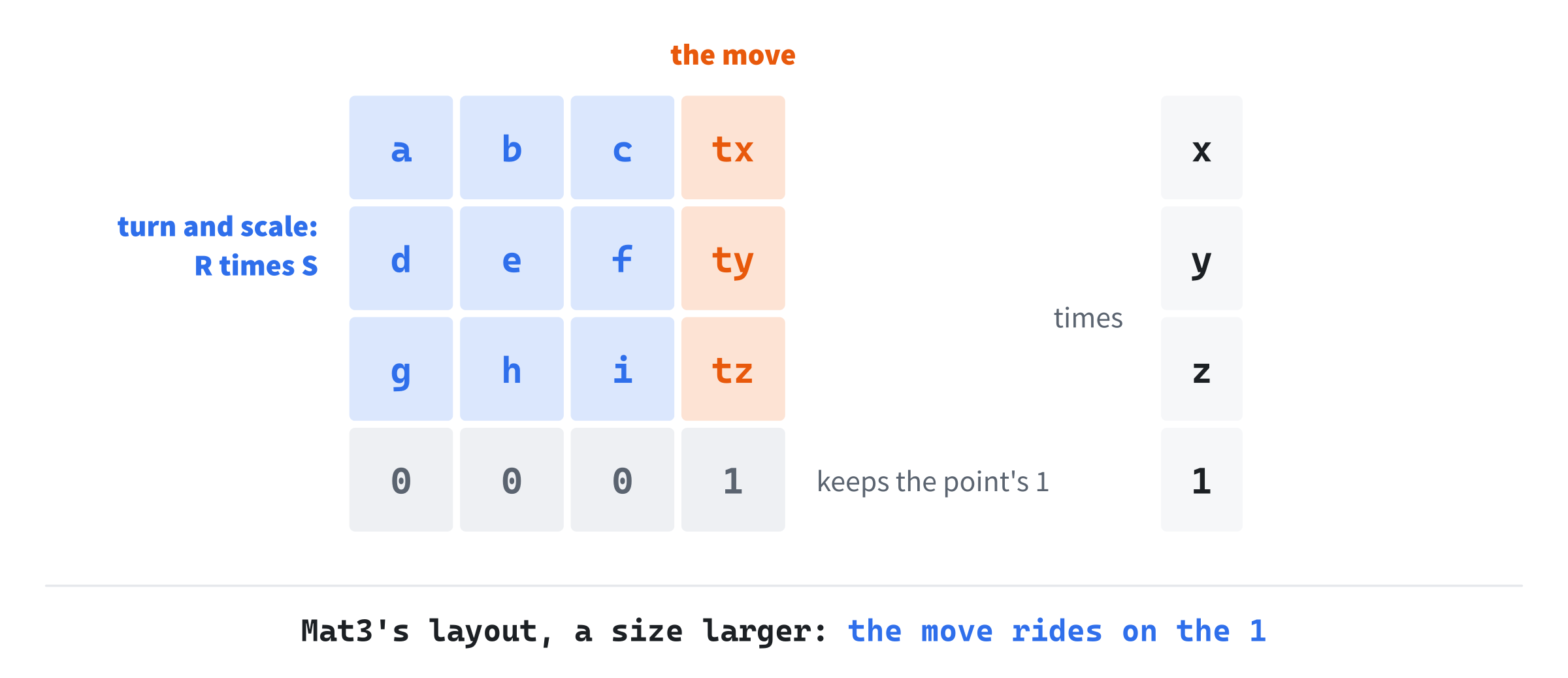
The 3 by 3 block, top left, holds the turn and the scale. For a matrix made as a move times a turn times a scale, the block is the turn times the scale. The fourth column holds the move. The bottom row stays 0, 0, 0, 1, so that the next matrix finds the 1 where it left it.
Mat4
This chapter's new header, Mat4.h, starts with the struct and its sixteen numbers:
#pragma once
#include <cmath>
#include "Vec3.h"

// Mat4: a 4 by 4 matrix, for transforms in 3D (Chapter 29). It's Mat3 a
// size larger. A point is the column (x, y, z, 1), and a matrix transforms
// it from the left. The bottom row is 0, 0, 0, 1 for every transform but a
// projection (Chapter 30). The numbers are kept by rows: m[row][column].
struct Mat4
{
    // A new Mat4 is the identity, which changes nothing.
    float m[4][4] = { { 1, 0, 0, 0 }, { 0, 1, 0, 0 }, { 0, 0, 1, 0 },
                      { 0, 0, 0, 1 } };
It's Mat3 with four of everything. The numbers are kept by rows, and a new Mat4 is the identity. The move and the scale come first, set into the identity as Mat3's were:
// A move by (tx, ty, tz), in the fourth column.
static Mat4 translation(float tx, float ty, float tz)
{
    Mat4 r;
    r.m[0][3] = tx;
    r.m[1][3] = ty;
    r.m[2][3] = tz;
    return r;
}

// A scale by sx, sy and sz, on the diagonal.
static Mat4 scale(float sx, float sy, float sz)
{
    Mat4 r;
    r.m[0][0] = sx;
    r.m[1][1] = sy;
    r.m[2][2] = sz;
    return r;
}
A move fills the fourth column's top three numbers, and a scale the diagonal's first three.
Turns About the Axes
Three Turns
In the plane, there was one turn, about the origin. In space, a turn is about an axis, and each of the three axes gives one. A turn about an axis leaves that axis alone, and turns the plane at right angles to it, just as Chapter 6 turned x and y. The next image shows the three, each counterclockwise as seen from its axis's positive end, as the right-hand rule says.
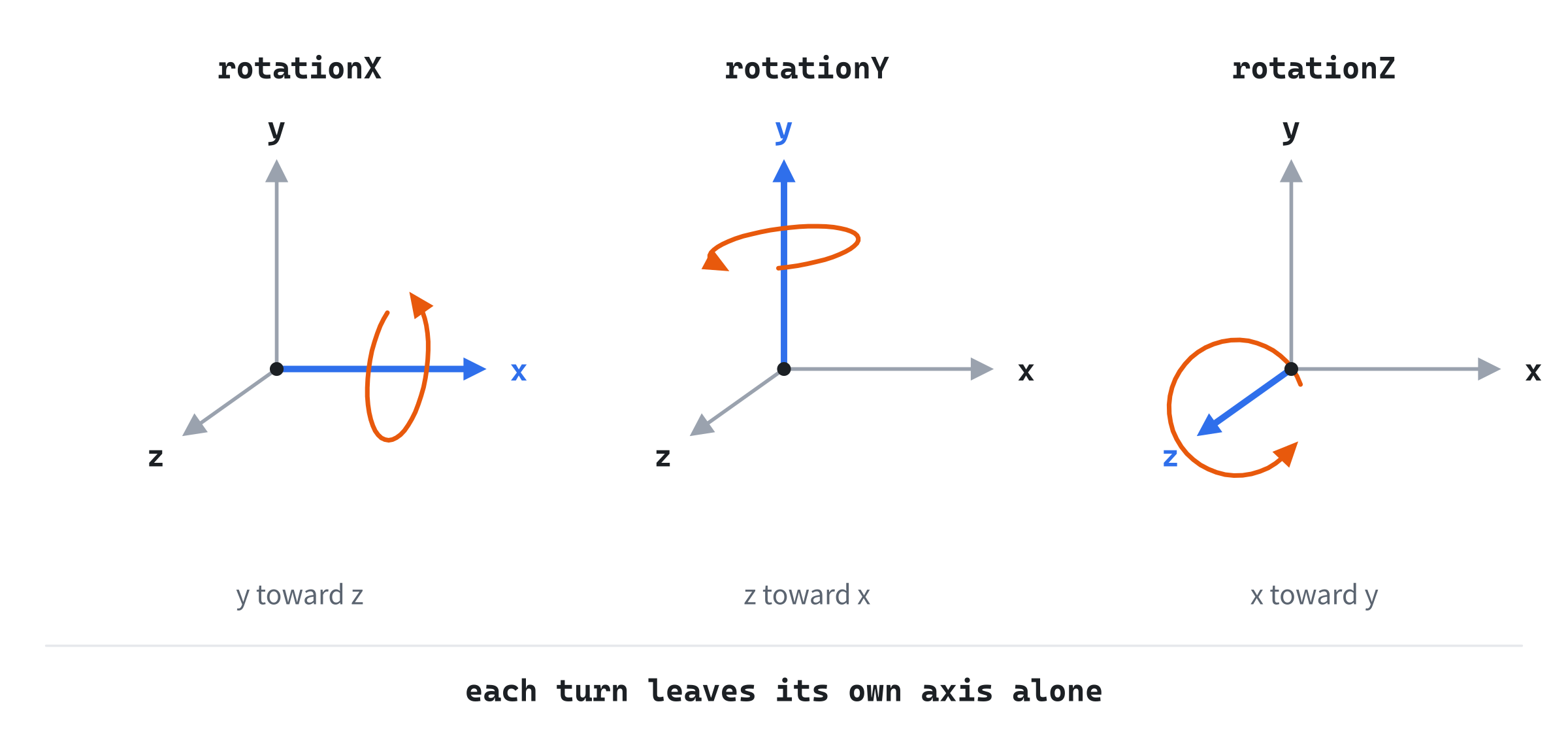
Each turn takes the axes in the cycle x, y, z, x. A turn about x turns y toward z, a turn about y turns z toward x, and a turn about z turns x toward y. Chapter 6's formulas, written for the pair that turns, give all three:
// Turns about the three axes, by an angle in radians, each one
// counterclockwise as seen from its axis's positive end. Each leaves its
// own axis alone, and turns the next two in the cycle x, y, z, x as
// Chapter 6 turned x and y: y and z for x, z and x for y, x and y for z.
static Mat4 rotationX(float a)
{
    float c = std::cos(a);
    float s = std::sin(a);
    Mat4 r;
    r.m[1][1] = c;
    r.m[1][2] = -s;
    r.m[2][1] = s;
    r.m[2][2] = c;
    return r;
}
The turn about x is Chapter 6's rotation, with y in place of x and z in place of y. It sets the four numbers where rows 1 and 2 meet columns 1 and 2. The turn about y works the same way on the pair z and x:
static Mat4 rotationY(float a)
{
    float c = std::cos(a);
    float s = std::sin(a);
    Mat4 r;
    r.m[2][2] = c;
    r.m[2][0] = -s;
    r.m[0][2] = s;
    r.m[0][0] = c;
    return r;
}
Its lines are in the pair's order, z first, which shows where its signs come from. Chapter 6's rotation gives z' = z cos - x sin and x' = z sin + x cos. Set into the matrix, the minus sign lands in row 2, below the diagonal, where the other two turns have their plus. So rotationY looks backward next to the others, but only because z comes before x in the cycle. The turn about z is the last:
static Mat4 rotationZ(float a)
{
    float c = std::cos(a);
    float s = std::sin(a);
    Mat4 r;
    r.m[0][0] = c;
    r.m[0][1] = -s;
    r.m[1][0] = s;
    r.m[1][1] = c;
    return r;
}
It leaves z alone and turns x and y, so its top-left corner is Chapter 6's rotation, exactly. Every turn in this book's 2D chapters was a turn about the z axis all along.
Applying It
Applying a Mat4 is Mat3's dot products, with a z:
// A point, transformed: each of the top three rows dotted with
// (x, y, z, 1), so the move in the fourth column is added.
Vec3 apply(Vec3 p) const
{
    return { m[0][0] * p.x + m[0][1] * p.y + m[0][2] * p.z + m[0][3],
             m[1][0] * p.x + m[1][1] * p.y + m[1][2] * p.z + m[1][3],
             m[2][0] * p.x + m[2][1] * p.y + m[2][2] * p.z + m[2][3] };
}

// A direction, transformed: each row dotted with (x, y, z, 0), so it's
// turned and scaled, but never moved.
Vec3 applyDir(Vec3 v) const
{
    return { m[0][0] * v.x + m[0][1] * v.y + m[0][2] * v.z,
             m[1][0] * v.x + m[1][1] * v.y + m[1][2] * v.z,
             m[2][0] * v.x + m[2][1] * v.y + m[2][2] * v.z };
}
The apply function treats its argument as a point, with a fourth coordinate of 1, so each line adds the move. The applyDir function treats it as a direction, with a 0, so the move doesn't appear. Neither works out the bottom row, since for every transform in this chapter it stays 0, 0, 0, 1. Chapter 30 meets a matrix whose bottom row does change, and handles it there.
The Product
The product is Mat3's, with four of everything:
// The product: one matrix that does b's transform, and then this
// one's, as Mat3's product, with four of everything.
Mat4 operator*(const Mat4& b) const
{
    Mat4 r;
    for (int i = 0; i < 4; ++i)
        for (int j = 0; j < 4; ++j)
        {
            float sum = 0.0f;
            for (int k = 0; k < 4; ++k) sum += m[i][k] * b.m[k][j];
            r.m[i][j] = sum;
        }
    return r;
}
Each of its 16 numbers is a dot product of 4 terms, so it takes 64 multiplications. That's still cheap next to what it saves: a cube's model matrix is built once a frame, and then each of its corners costs 9 multiplications.
The Columns Are the Axes
Chapter 26 found that a matrix's columns are where it sends the axes. For a turn, that means its first three columns are the turned object's own x, y and z axes, seen from the world. After the struct's closing brace, a free function reads a column:
};

// Column j of a matrix's 3 by 3 block: where the matrix sends axis j. For
// a turn, it's the turned object's own axis.
inline Vec3 column(const Mat4& a, int j)
{
    return { a.m[0][j], a.m[1][j], a.m[2][j] };
}
A turn's columns are each 1 long, and each at right angles to the other two, since turning keeps lengths and angles. That's what makes a turn easy to undo. Chapter 31 finds that a turn's inverse is its transpose, the same numbers with its rows and columns swapped.
The Model Matrix
A Move, a Turn and a Scale
An object's model matrix places it in the world. It takes the object's corners from its own space, its model space, to where the object is, turned and sized as it should be. It's built as Chapter 26 built Matrix Sandbox's:
model = T R SRead from the right, a corner is scaled first, while the object is still around the origin. Then it's turned about the origin, and moved to its place. Take a cube's corner at (1, 1, 1), with a scale of 2, a quarter turn about y and a move to (3, 0, 0). The scale takes the corner to (2, 2, 2). The quarter turn takes it to (2, 2, -2), since it sends z toward x and x toward -z. The move takes it to (5, 2, -2).
The Other Order
Swap the move and the turn, as R T S, and the corner is moved before it's turned. The move takes (2, 2, 2) to (5, 2, 2), and the turn then swings that about the origin, to (2, 2, -5). The whole cube goes with it: R T S turns the cube's position about the origin, as well as the cube. So a cube placed by T R S turns in place, and one placed by R T S orbits the origin. The next image shows both, seen from above.
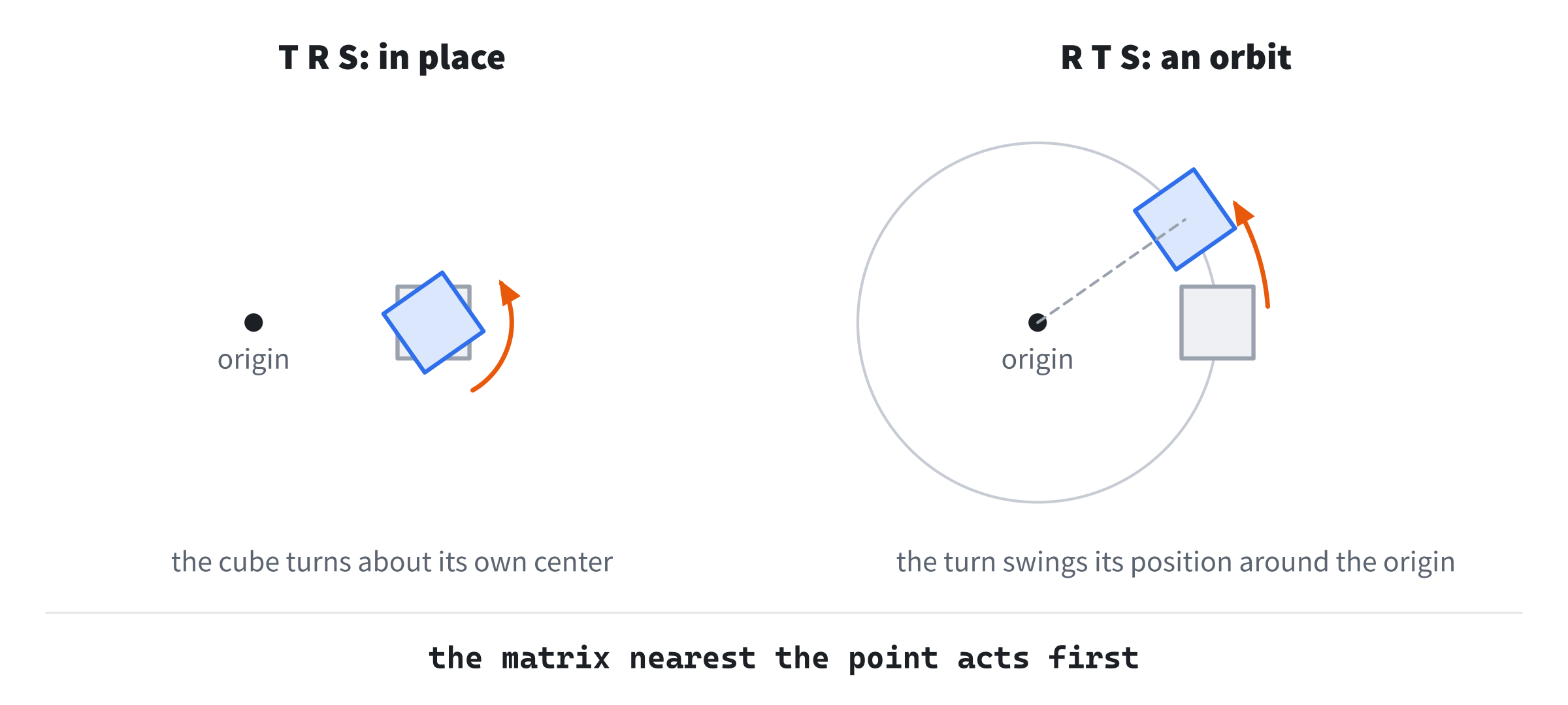
Neither order is wrong. T R S is the usual model matrix, and R T S is how a planet goes around a sun, as Chapter 25's scene graph did.
Three Angles
Euler Angles
One common way to describe an object's turn is three angles, one about each axis, multiplied together:
R = Rz Ry RxRead from the right, that turns the object about x first, then y, then z. Each turn is about the world's fixed axes. These are Euler angles, and they're easy to think about: a yaw, a pitch and a roll. Transforming a Cube turns its cube this way.
Their Order Matters
Turns about different axes don't share their order. Take the point (0, 0, 1) and two quarter turns, about y and about x. Turned about y first, as Rx Ry, it goes to (1, 0, 0). The turn about x then leaves it there, since it lies along x. Turned about x first, as Ry Rx, it goes to (0, -1, 0), and the turn about y leaves that alone. The next image shows the same pair of turns, in the two orders, on a cube with a mark.
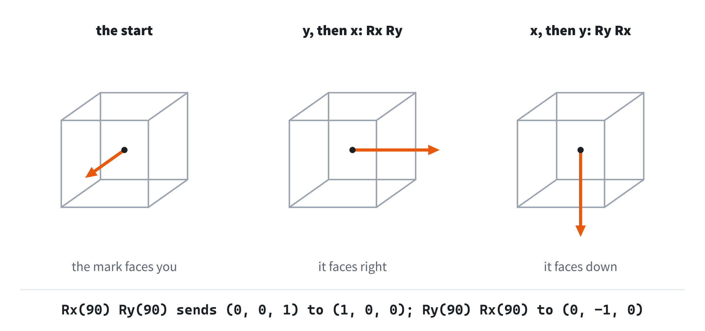
So Euler angles always come with an order. Rz Ry Rx is one choice of six, and an engine, a file format and an artist have to agree on which one they mean, or the same three angles turn an object differently.
Gimbal Lock
There's a worse problem. At some turns, two of the three angles turn the object about the same axis, and a direction of turning is lost. Set the turn about y to a quarter turn, and multiply the three out:
Rz(γ) Ry(90°) Rx(α) = | 0   sin(α - γ)   cos(α - γ) |
                      | 0   cos(α - γ)  -sin(α - γ) |
                      | -1      0            0      |
Only the difference α - γ appears. Any rx and rz with the same difference give the same matrix: 0.6 and 0.3 give exactly what 0.9 and 0.6 give. So at that turn, changing rx and changing rz do the same thing, turning the cube about one axis. No setting of the three angles can turn it about the axis that's been lost, until the turn about y moves away from 90 degrees. That's gimbal lock, named for the rings of a gyroscope, which line up and jam in the same way.
Euler angles are fine for a cube a player turns by hand, or a camera that never looks straight up. For an aircraft or an animation that can turn any way, they jam. Chapter 35 builds quaternions, which hold a whole turn at once and never lock.
Rebuild, Don't Pile Up
Transforming a Cube builds its turn afresh each frame, from its three angles. It doesn't multiply last frame's turn by a small new one, though that looks simpler. Floats are rounded at every product, and the errors pile up. Measured, a turn built that way has columns 0.99995 long after ten thousand frames, and 0.995 long after a million. By then they're no longer quite at right angles, so the object has shrunk and slanted by half a percent. Rebuilding from the angles each frame starts fresh every time. A game that must pile turns up, as one following a player's mouse might, corrects them now and then, or keeps them as quaternions.
Normals Under an Uneven Scale
A matrix with an uneven scale moves a surface's normal the wrong way. Take the plane x + y = 0, which holds the direction (1, -1, 0) and has the normal (1, 1, 0). Stretch it to twice its width with a scale of (2, 1, 1). The direction in the plane becomes (2, -1, 0), but applyDir takes the normal to (2, 1, 0), and the dot product of those two is 3, not 0. The stretched normal is no longer at right angles to its surface. The right matrix for normals is the inverse of the model matrix's block, transposed, which for this scale is a scale of (0.5, 1, 1). That gives (0.5, 1, 0), and a dot product of 0. Chapter 33 sidesteps the problem: it works out each triangle's normal afresh from its corners after they're transformed, as Chapter 28 did.
Building Transforming a Cube
Transforming a Cube draws a wireframe cube, placed by one model matrix. Drag to turn it about x and y, hold Z and X to turn it about z, and hold Up and Down to scale it. WASD moves it in x and y, and Q and E move it in z. O swaps the order to R T S, so that it orbits the origin. G sets the turn about y to a quarter turn, where it locks. The cube's own axes are drawn from the columns of its turn, and the readout shows its matrix.
Get the code. The complete project is in the
Transforming a Cubefolder of the book's repository.
Transforming a Cube starts from the skeleton, with its timing. It reads the mouse's movement but not its position, as Normals did. It reuses drawArrow from Chapter 2, fmt2 from Chapter 4, padded from Chapter 26 and project from Chapter 28. Its Vec2.h and Vec3.h are Normals', and its Mat4.h is the one this chapter built. Here are its includes and its colors:
#include <cmath>
#include <string>
#include "Vec2.h"
#include "Vec3.h"
#include "Mat4.h"

constexpr int WINDOW_WIDTH  = 1000;
constexpr int WINDOW_HEIGHT = 700;

constexpr SDL_Color TEXT = { 235, 238, 242, 255 };
constexpr SDL_Color GREY = { 90, 100, 112, 255 };
constexpr SDL_Color RED = { 235, 80, 80, 255 };
constexpr SDL_Color GREEN = { 60, 190, 100, 255 };
constexpr SDL_Color BLUE = { 90, 150, 240, 255 };
constexpr SDL_Color AMBER = { 240, 200, 60, 255 };
The cube's x axis is red, its y axis green and its z axis blue, and the note about gimbal lock is amber. Then come the constants:
// The view: pixels for each unit of the world, and where the world's
// origin is in the window. Then how fast things change, a second: the spin,
// the turn about z, the move and the scale; how far a drag turns, a pixel;
// and the scale's limits.
constexpr float SCALE = 110.0f;
constexpr float CX = 380.0f;
constexpr float CY = 360.0f;
constexpr float SPIN_X = 0.25f;
constexpr float SPIN_Y = 0.6f;
constexpr float TURN_SPEED = 1.2f;
constexpr float MOVE_SPEED = 2.0f;
constexpr float SCALE_SPEED = 0.8f;
constexpr float DRAG_TURN = 0.01f;
constexpr float MIN_SCALE = 0.3f;
constexpr float MAX_SCALE = 2.2f;
Each unit is 110 pixels, and the origin is at (380, 360), as in Normals. The cube spins at 0.6 radians a second about y and 0.25 about x, and Z and X turn it at 1.2. It moves 2 units a second, and scales by 0.8 a second, from 0.3 up to 2.2.
The State
The state goes after the font is loaded:
// The cube in its own space: eight corners at every mix of -1 and 1,
// and its twelve edges, as pairs of corners: the four of its back face,
// the four of its front, and the four that join them.
const Vec3 CORNER[8] = { { -1, -1, -1 }, { 1, -1, -1 }, { 1, 1, -1 },
                         { -1, 1, -1 }, { -1, -1, 1 }, { 1, -1, 1 },
                         { 1, 1, 1 }, { -1, 1, 1 } };
const int EDGE[12][2] = { { 0, 1 }, { 1, 2 }, { 2, 3 }, { 3, 0 },
                          { 4, 5 }, { 5, 6 }, { 6, 7 }, { 7, 4 },
                          { 0, 4 }, { 1, 5 }, { 2, 6 }, { 3, 7 } };

// The cube's place, its three turns in radians, and its scale; whether
// it spins, whether its matrix is built in the orbit's order, and
// whether it's being dragged.
Vec3 pos = { 0.0f, 0.0f, 0.0f };
float rx = 0.5f;
float ry = 0.6f;
float rz = 0.0f;
float s = 1.0f;
bool spin = true;
bool orbit = false;
bool dragging = false;
In the preceding code, the cube's eight corners are every mix of -1 and 1, so it's 2 units on a side, around its own origin. Its twelve edges are pairs of corner numbers: the back face's four, the front face's four, and the four that join them. A list of corners and a list of what joins them is the simplest mesh, and Chapter 32 grows it into one that holds triangles. The cube starts at the origin, turned 0.5 about x and 0.6 about y, at a scale of 1.
The Events
The keys spin, swap the order, lock and reset, and a drag turns the cube:
// Events: quitting, and the keys and clicks that happen once. A drag
// turns the cube about y as the mouse moves across, and about x as it
// moves down.
SDL_Event event;
while (SDL_PollEvent(&event))
{
    if (event.type == SDL_EVENT_QUIT) running = false;
    else if (event.type == SDL_EVENT_KEY_DOWN)
    {
        if (event.key.key == SDLK_ESCAPE) running = false;
        else if (event.key.key == SDLK_SPACE) spin = !spin;
        else if (event.key.key == SDLK_O) orbit = !orbit;
        else if (event.key.key == SDLK_G)
        {
            rx = 0.0f;
            ry = PI / 2.0f;
            rz = 0.0f;
            spin = false;
        }
        else if (event.key.key == SDLK_R)
        {
            pos = { 0.0f, 0.0f, 0.0f };
            rx = 0.5f;
            ry = 0.6f;
            rz = 0.0f;
            s = 1.0f;
            spin = true;
            orbit = false;
        }
    }
    else if (event.type == SDL_EVENT_MOUSE_BUTTON_DOWN &&
             event.button.button == SDL_BUTTON_LEFT)
    {
        dragging = true;
        spin = false;
    }
    else if (event.type == SDL_EVENT_MOUSE_BUTTON_UP) dragging = false;
    else if (event.type == SDL_EVENT_MOUSE_MOTION && dragging)
    {
        ry += event.motion.xrel * DRAG_TURN;
        rx += event.motion.yrel * DRAG_TURN;
    }
}
In the preceding code, G sets the turn about y to a quarter turn, π over 2, and the other two turns to 0. It stops the spin too, so that the lock holds still to be explored. R puts everything back as it started. A drag turns the cube about y as the mouse moves across, and about x as it moves down, a hundredth of a radian a pixel.
Each Frame's Work
Each frame, the keys that are held change the parts, and the turns are wrapped:
// Keys held down scale the cube, move it, and turn it about z, and it
// spins while it's left alone. The turns are wrapped, so that the
// readout stays between -180 and 180 degrees.
const bool* keys = SDL_GetKeyboardState(nullptr);
if (keys[SDL_SCANCODE_UP]) s += SCALE_SPEED * dt;
if (keys[SDL_SCANCODE_DOWN]) s -= SCALE_SPEED * dt;
s = SDL_clamp(s, MIN_SCALE, MAX_SCALE);
if (keys[SDL_SCANCODE_A]) pos.x -= MOVE_SPEED * dt;
if (keys[SDL_SCANCODE_D]) pos.x += MOVE_SPEED * dt;
if (keys[SDL_SCANCODE_W]) pos.y += MOVE_SPEED * dt;
if (keys[SDL_SCANCODE_S]) pos.y -= MOVE_SPEED * dt;
if (keys[SDL_SCANCODE_Q]) pos.z -= MOVE_SPEED * dt;
if (keys[SDL_SCANCODE_E]) pos.z += MOVE_SPEED * dt;
if (keys[SDL_SCANCODE_Z]) rz -= TURN_SPEED * dt;
if (keys[SDL_SCANCODE_X]) rz += TURN_SPEED * dt;
if (spin)
{
    ry += SPIN_Y * dt;
    rx += SPIN_X * dt;
}
rx = wrapAngle(rx);
ry = wrapAngle(ry);
rz = wrapAngle(rz);
In the preceding code, the scale is clamped after Up or Down changes it. W and S move the cube up and down, since y points up in the world, and E and Q move it nearer and farther. Chapter 5's wrapAngle, from Vec2.h, keeps each turn between -π and π. Then the model matrix is built from its parts:
// The model matrix, from its parts. T * R * S turns the cube in
// place; R * T * S turns its position too, so that it orbits.
Mat4 R = Mat4::rotationZ(rz) * Mat4::rotationY(ry) *
         Mat4::rotationX(rx);
Mat4 T = Mat4::translation(pos.x, pos.y, pos.z);
Mat4 S = Mat4::scale(s, s, s);
Mat4 model = orbit ? (R * T * S) : (T * R * S);
The turn is Rz Ry Rx, the scale is the same each way, and the order is T R S, or R T S after O.
Drawing
After the skeleton clears the screen, the edges are drawn:
// The twelve edges, each corner taken into the world by the model
// matrix. An edge nearer than the cube's center is brighter, and one
// farther is dimmer, which the projection, dropping z, can't show.
Vec3 center = model.apply({ 0.0f, 0.0f, 0.0f });
for (int e = 0; e < 12; ++e)
{
    Vec3 a = model.apply(CORNER[EDGE[e][0]]);
    Vec3 b = model.apply(CORNER[EDGE[e][1]]);
    float depth = ((a.z + b.z) * 0.5f - center.z) / s;
    float shade = SDL_clamp(0.62f + depth * 0.22f, 0.3f, 1.0f);
    SDL_SetRenderDrawColor(renderer, (Uint8)(110 * shade),
                           (Uint8)(170 * shade), (Uint8)(240 * shade),
                           255);
    Vec2 pa = project(a);
    Vec2 pb = project(b);
    SDL_RenderLine(renderer, pa.x, pa.y, pb.x, pb.y);
}
The model matrix takes each edge's two corners into the world, and project puts them on the window. The view drops z, so it can't show which edges are nearer, but the shade can. An edge's depth is its middle's z, measured from the cube's center and divided by the scale, so it runs from about -1.4 to 1.4. Nearer edges are drawn brighter and farther ones dimmer, which lets a flat wireframe read as solid. Since the depth is measured from the cube's center, moving the whole cube nearer or farther changes nothing on the window. Then come the cube's own axes:
// The cube's own axes, from its center: the columns of its turn, R,
// in red, green and blue, as long as the cube is from its center to
// the middle of a face, and half again.
Vec2 from = project(center);
float arm = 1.5f * s;
drawArrow(renderer, from, project(center + column(R, 0) * arm), RED);
drawArrow(renderer, from, project(center + column(R, 1) * arm), GREEN);
drawArrow(renderer, from, project(center + column(R, 2) * arm), BLUE);
Each arrow runs from the cube's center along a column of R, the cube's own axis, 1.5 times the scale long, so that it pokes out of the cube. Last come the readout and the controls:
// The readout: the order, then the model matrix, with its first three
// columns in the colors of the axes they hold, and the move in the
// fourth. Then the turns, the place and the scale, and a note when
// the turn about y is a quarter turn either way.
drawText(renderer, font,
         orbit ? "M = R * T * S: orbit" : "M = T * R * S: in place",
         640, 40, TEXT);
const SDL_Color COLUMN[4] = { RED, GREEN, BLUE, TEXT };
for (int i = 0; i < 4; ++i)
    for (int j = 0; j < 4; ++j)
        drawText(renderer, font, padded(model.m[i][j], 2),
                 640 + j * 86.0f, 64 + i * 22.0f, COLUMN[j]);
drawText(renderer, font,
         "turns rx " + std::to_string((int)std::lround(rx * 180 / PI)) +
         ", ry " + std::to_string((int)std::lround(ry * 180 / PI)) +
         ", rz " + std::to_string((int)std::lround(rz * 180 / PI)) +
         " degrees", 640, 162, TEXT);
drawText(renderer, font,
         "place (" + fmt2(pos.x) + ", " + fmt2(pos.y) + ", " +
         fmt2(pos.z) + "), scale " + fmt2(s), 640, 184, TEXT);
if (std::fabs(std::fabs(ry) - PI / 2.0f) < 0.02f)
    drawText(renderer, font, "ry is 90: rx and rz share an axis",
             640, 216, AMBER);
drawText(renderer, font,
         "[Drag] turn   [Z] [X] turn about z   [Space] spin   "
         "[Up] [Down] scale", 12, WINDOW_HEIGHT - 46, GREY);
drawText(renderer, font,
         "[WASD] [Q] [E] move   [O] order   [G] ry 90   [R] reset   "
         "[Esc] quit", 12, WINDOW_HEIGHT - 26, GREY);
In the preceding code, each of the model matrix's numbers is drawn on its own, 86 pixels apart, with padded from Chapter 26. The first three columns are in the colors of the axes they hold, and the fourth, the move, is white. The turns are shown in whole degrees. The note appears when the turn about y is within 0.02 radians of a quarter turn either way. There's nothing to add to the skeleton's cleanup.
Trying It Out
Run the demo. The cube tumbles slowly, with its red, green and blue axes riding along. Then try it, step by step:
- Read the columns. Press Space to stop the spin. The matrix's red column is the red arrow's direction, the green column the green arrow's, and the blue column the blue arrow's. Turn the cube with a drag, and the columns and the arrows change together.
- Scale and move it. Hold Up, and the first three columns grow together, since T R S puts the scale into all three. Hold D, and only the fourth column's top number changes: the move.
- Move it in z. Hold Q or E. The fourth column's z changes, but nothing on the window does, since the projection drops z, and the shading is measured from the cube's own center. Chapter 30 fixes the projection.
- Make it orbit. Move the cube to the right with D, then press O for R T S, and press Space to spin. The cube swings around the origin as it turns. Hold Q or E now, and the cube does move on the window, since the turn swings its z into x and y.
- Lock it. Press R, then G. The turn about y is now a quarter turn, and the red arrow has vanished: the cube's own x axis points straight away from you. Drag up and down, which changes rx, and the cube spins in the window's plane. Hold Z or X, which changes rz, and it spins in the same plane, about the same axis. Two of the three knobs now turn the cube the same way.
- Roll it. While it's locked, notice what a vertical drag does. Before G, it tipped the cube toward you. Now it rolls the cube like a wheel, since the turn about x comes first, about the cube's own x axis, which now points away from you.
The next image shows step 2, with the cube moved to (0.8, 0.3, 0).
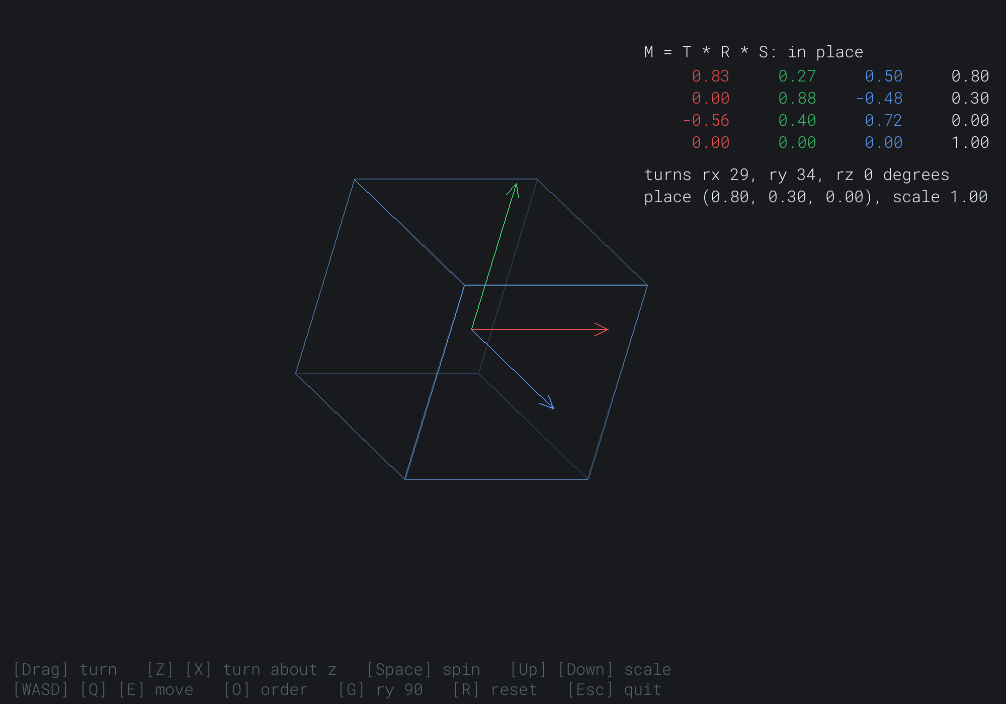
The red column, (0.83, 0.00, -0.56), is the cube's x axis. It's turned 34 degrees about y, so it points right and a little away from you. The fourth column is the move, (0.80, 0.30, 0.00). The next image shows step 5, with rx at 0.6 and rz at 0.3, after G.
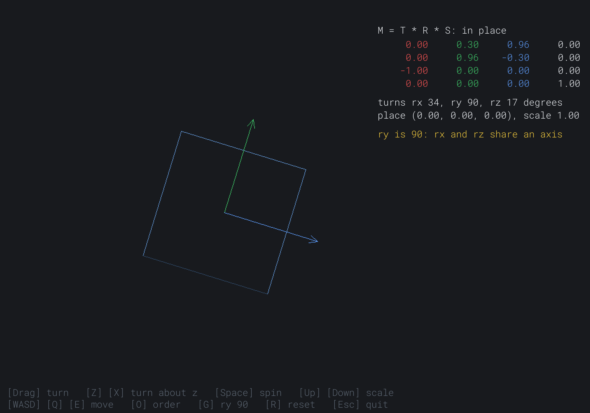
The first column is (0, 0, -1): the cube's x axis points straight away from you, so its arrow is a point. The other two columns hold sin 0.3 and cos 0.3, about 0.30 and 0.96, from the difference between rx and rz. Setting rx to 0.9 and rz to 0.6 gives exactly this matrix again.
FAQ
Q) Which order of Euler angles should I use?
A) Any one, as long as it's fixed and everyone who reads your angles knows it. The order decides which axis each angle turns about, and where the lock falls. Many first-person games put the yaw, the turn about the vertical axis, outermost, and the pitch next. The lock then falls at a pitch of 90 degrees, looking straight up or down, so they stop the pitch just short of it.
Q) Where's the inverse of a Mat4?
A) Chapter 26's 2 by 2 formula doesn't stretch to 3 by 3 so simply, and this book never needs a general 3D inverse. A model matrix's inverse is its parts undone in reverse order: the inverse of T R S is S⁻¹ Rᵀ T⁻¹, where Rᵀ, the turn transposed, is its inverse. Chapter 31's camera builds its inverse that way, from the start.
Exercises
The first three exercises need only a pencil. The others change Transforming a Cube.
- Turn by hand (paper). Write out the 4 by 4 matrix for a quarter turn about z, and apply it to
(1, 0, 0). Check it against Chapter 6's rotation, with z left alone. - The other order (paper). For the corner
(1, 1, 1), a scale of 2, a quarter turn about x and a move to(0, 3, 0), find where T R S and R T S each put the corner. - Lock by hand (paper). Multiply Rx(α) by Ry(90°) by Rz(γ), the other order, and find which combination of α and γ survives.
- Another order (code). Build the turn as Rx Ry Rz instead, and find the turn about y where it locks now. Does G still lock it?
- Pile it up (code). Add a key that switches to turning the cube by multiplying last frame's turn by a small new one. Print the length of column 0 every second, and watch it drift.
- A stretched cube's normals (challenge). Give the turned cube a stretch of
(2, 1, 1)after its turn, as T S R. Draw each face's normal from its middle, transformed byapplyDir. Then draw them again, turned by R and scaled by(0.5, 1, 1), and see which ones stay at right angles to their faces.
For the code exercises, work on a copy of the demo's folder, so that the original stays as the chapter describes it.
AI Exercise (Optional)
A model matrix for each part makes a little machine that moves. With an AI's help, you can build a robot arm on Mat4. Open your AI chatbot of choice, and try a prompt like this:
"I have a C++ demo using SDL3, in a 1000 by 700 window, with a struct Vec3 and a struct Mat4, a 4 by 4 matrix stored as m[row][column], with static translation, scale, rotationX, rotationY and rotationZ, operator* for the product, apply(p) for points and applyDir(v) for directions, and a free function column(M, j). I draw by an orthographic projection that drops z, in a right-handed world with y up. Please make a robot arm of three boxes, drawn as wireframes: a base that turns about y, an upper arm that turns about z at the top of the base, and a forearm that turns about z at the end of the upper arm. Each part's matrix is its parent's matrix times its own move and turn. Keys turn each joint, within limits. Draw each part's own axes from the columns of its matrix, and show the hand's position in the world. Then add a key that makes the arm reach for a point by turning its joints a little each frame toward it. Explain why the forearm follows when the base turns."
That prompt describes the matrix you built, so the AI builds on it, rather than writing its own. The arm is Chapter 25's scene graph, done with Chapter 29's matrices: each part's matrix is its parent's times its own. The axes from the columns show each joint's frame as it turns.
Then turn the base until the arm points straight up, and look for a lock of its own. Then add a fourth joint, a wrist that turns about the forearm's own x axis.
Summary
Points in 3D get a fourth coordinate, a 1, so that a move can ride in a matrix, and their transforms are 4 by 4. A Mat4 is a Mat3 with four of everything. It has a 3 by 3 block for the turn and the scale, a fourth column for the move and a bottom row of 0, 0, 0, 1. The product, apply and applyDir work as before. A turn in space is about an axis. Each of the three leaves its own axis alone, and turns the next two in the cycle of the axes, by Chapter 6's formulas. That cycle is why rotationY's signs look backward, and rotationZ is Chapter 6's rotation exactly. A turn's columns are the turned object's own axes. A model matrix, T R S, scales, turns and then moves an object's corners. R T S turns its position too, so that it orbits. Euler angles turn about the three axes in turn, so their order matters, and at a quarter turn about y, two of them turn about the same axis: gimbal lock. A turn built afresh each frame doesn't drift, and normals under an uneven scale need the inverse, transposed. Chapter 30 stops dropping z, and makes distant things smaller, with a perspective projection.